

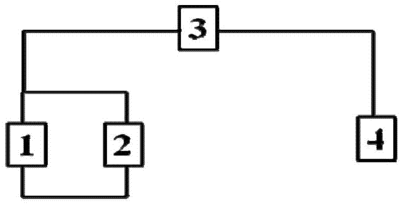
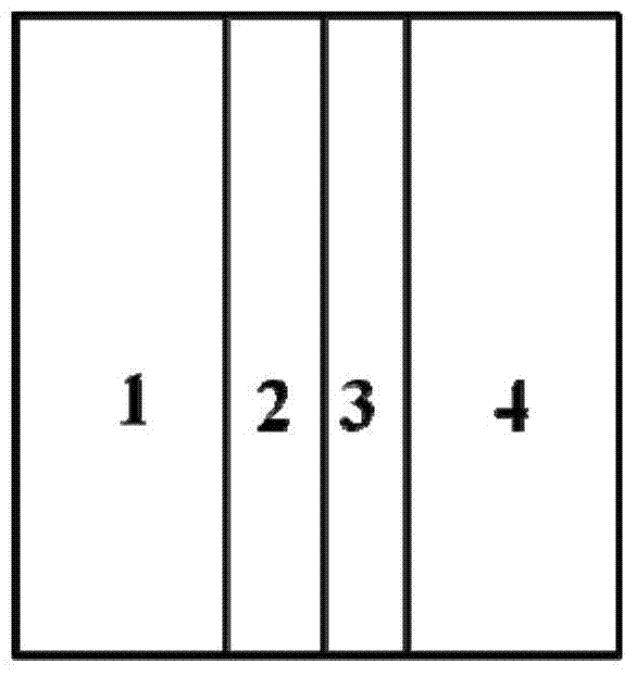
Lithium-air battery structure
An air battery, lithium negative electrode technology, applied in battery electrodes, structural parts, circuits, etc., can solve the problems of complex process and limited time for effect maintenance.
- Summary
- Abstract
- Description
- Claims
- Application Information
AI Technical Summary
Problems solved by technology
Method used
Image

Examples
Embodiment 1
[0025] Blend 100mg KB600 carbon powder with polytetrafluoroethylene emulsion (PTFE, 5% mass fraction) in ethanol to obtain electrode slurry, wherein the mass ratio of carbon powder to polytetrafluoroethylene is 4:1, solid matter The ratio of the solvent to the solvent is 20 mg solid / ml solvent; the flake carbon layer is prepared by rolling, and dried at 60 degrees Celsius. The surface density of the carbon material in the carbon layer is 0.5 mg / cm 2 .
[0026] Using KB600 as the electrode material, the same process as above was used to prepare the positive electrode for lithium-air batteries, wherein the areal density of the carbon material was 3 mg / cm 2 .
[0027] Using 1M LiTFSI / TEGDME as the electrolyte, the metal lithium negative electrode, porous carbon layer, porous polypropylene separator, and positive electrode were laminated in sequence to assemble a lithium-air single cell. In a pure oxygen atmosphere of 1.2 atmospheres, a current density of 50mA / g (based on the ma...
Embodiment 2
[0029] Blend 100mg of graphene and polytetrafluoroethylene emulsion (PTFE, 5% mass fraction) in ethanol to obtain electrode slurry, wherein the mass ratio of graphene to polytetrafluoroethylene is 5:1, solid matter and The solvent ratio is 15 mg solid / ml solvent; the sheet-like carbon layer is prepared by rolling, and dried at 60 degrees Celsius. The surface density of the carbon material in the carbon layer is 0.5 mg / cm 2 .
[0030] The positive electrode for the lithium-air battery was prepared by the same process as in Example 1, the single cell was assembled by the same process, and the cycle test was carried out by the same charge and discharge mechanism. Compared with the non-functional layer battery structure, when the discharge cut-off voltage is 2V, the number of cycles when the discharge capacity is lower than 1000mAh / g is increased by 25.
Embodiment 3
[0032] Blend 100mg of carbon nanotubes and PVDF in NMP at a mass ratio of 5:1 to obtain an electrode slurry, the ratio of solid matter to solvent is 15mg solid / ml solvent; using a scraper coating method, prepare a flake on the surface of porous polypropylene Carbon layer, dried at 60 degrees Celsius, the surface density of carbon material in the carbon layer is 0.5mg / cm 2 .
[0033] The positive electrode for the lithium-air battery was prepared by the same process as in Example 1, the single cell was assembled by the same process, and the cycle test was carried out by the same charge and discharge mechanism. Compared with the non-functional layer battery structure, when the discharge cut-off voltage is 2V, the number of cycles when the discharge capacity is lower than 1000mAh / g is increased by 27.
PUM
| Property | Measurement | Unit |
|---|---|---|
| Areal density | aaaaa | aaaaa |
| Areal density | aaaaa | aaaaa |
Abstract
Description
Claims
Application Information