Contaminated soil remediation system

A technology for remediating systems and polluted soil, applied in the restoration of polluted soil, etc., can solve the problems of inability to separate inorganic substances, waste of energy, and high production costs, and achieve the goal of avoiding pollution and transshipment costs, broad market prospects, and low manufacturing costs Effect

Active Publication Date: 2015-07-22
重庆化医太湖锅炉股份有限公司 +1
View PDF9 Cites 23 Cited by
  • Summary
  • Abstract
  • Description
  • Claims
  • Application Information

AI Technical Summary

Problems solved by technology

[0004] (1) The soil is not pretreated before the thermal desorption of the soil, so that the direct heating desorption process takes a long time, consumes a lot of energy, and has low efficiency. At the same time, due to the low temperature, only the organic matter in the soil can be separated. It is impossible to separate the inorganic substances in the soil;
[0005] (2) The flue gas produced in the thermal desorption process is not utilized for waste heat, and is directly discharged into the air. On the one hand, it does not meet the national temperature requirements for the exhaust gas, and on the other hand, it also wastes energy;
[0006] (3) The desorbed pollutants need to be transported and then incinerated. The cost of transport and storage is high, and there are also problems such as secondary pollution;
[0007] (4) In addition, there are still problems such as high production cost and high cost, and the effect of soil restoration needs to be improved

Method used


Image

  • Contaminated soil remediation system

Examples


Embodiment Construction

[0027] Below by embodiment and in conjunction with accompanying drawing, the present invention will be further described:

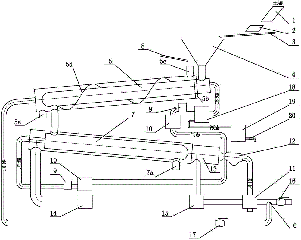
[0028] like figure 1 As shown, a contaminated soil remediation system consists of a sorter 1, a crusher 2, a second conveyor belt 3, a feed bin 4, a waste heat rotary kiln 5, a tee pipe 6, a thermal desorption rotary kiln 7, and a first conveyor belt 8. Fan 9, buffer tank 10, air preheater 11, burner 12, combustion chamber 13, induced draft fan 14, regulating distributor 15, exhaust valve 16, smoke volume regulating valve 17, condensation separator 18, waste liquid tank 19. The drain valve 20 and other components.

[0029] Both the waste heat rotary kiln 5 and the heat desorption rotary kiln 7 are double-layered, including an inner tank and an outer shell, and the space between the inner tank and the outer shell is large enough. The feed end of the waste heat rotary kiln 5 and the heat desorption rotary kiln 7 are higher than the discharge end, so that ...


PUM


Abstract

The invention discloses a contaminated soil remediation system. Soil is sequentially fed into the inner container of a waste heat rotary kiln through a feeding cabin, the inner container of a heat desorption rotary kiln, and the interlayer of the waste heat rotary kiln through a first conveyer belt, and is finally discharged out through a first soil outlet; air is fed into a combustion chamber for combustion through a combustor; generated fume is fed into the interlayer of the heat desorption rotary kiln to make straight line movement, is further accessed to the interlayer of the waste heat rotary kiln through a pipeline to make spiral movement, and is finally discharged out through a fume outlet formed in the shell of the waste heat rotary kiln; the waste gas generated in the inner container of the heat desorption rotary kiln is accessed to the combustor for incineration; the waste gas generated in the inner container of the waste heat rotary kiln is accessed to a condensation separator through a pipeline; the gas separated in the condensation separator is accessed to the combustion for incineration through another pipeline; a liquid separated in the condensation separator is discharged out through another pipeline. The contaminated soil remediation system has the characteristics of low energy consumption, high efficiency, low manufacturing cost, high easiness to implement, good remediation effect and the like, and has wide market prospect.

Description

technical field [0001] The invention relates to the field of soil remediation, in particular to a remediation system for polluted soil. Background technique [0002] The soil is originally a natural shelter and purification treatment site for various wastes. When the soil contains too many pollutants, which affects or exceeds the self-purification ability of the soil, the soil itself also needs to be repaired. There are many reasons for soil pollution, such as industrial sludge, agricultural garbage, sewage irrigation, pollutant deposition in the atmosphere, heavy use of mineral fertilizers and pesticides containing heavy metals, and so on. Nearly one-fifth of China's existing arable land is polluted to varying degrees. Polluted soil will lead to crop yield reduction, and may even cause pollutants in agricultural products to exceed the standard, thereby endangering human health. In addition, with the acceleration of economic development and urbanization, the site pollution ...

Claims


Application Information

Patent Timeline
Patent Type & Authority Applications(China)
IPC IPC(8): B09C1/00
Inventor 李正斌高春森汪亚平
Owner 重庆化医太湖锅炉股份有限公司
Why Eureka
Try Eureka