Method and device for preparing rare-earth metal through lower cathode electrolysis and in-situ ingot casting synchronization

A technology of rare earth metal and cathodic electrolysis, which is applied in the direction of cells, etc., can solve the problems of difficult operation for workers, enlarged cell scale, and high comprehensive cost, so as to improve surface quality and internal crystallization structure, improve quality and yield, and solve furnace problems. The effect of large temperature fluctuations

Active Publication Date: 2015-07-29
JIANGXI UNIV OF SCI & TECH
View PDF6 Cites 14 Cited by
  • Summary
  • Abstract
  • Description
  • Claims
  • Application Information

AI Technical Summary

Problems solved by technology

[0003] The shortcomings of the first type of electrolytic cell mainly include the following points: first, during the electrolysis process, with the consumption of the anode, the pole distance increases continuously, and the voltage also increases, resulting in serious power loss; second , the lower end of the upper inserted cathode is soaked under the liquid surface, and the rest is exposed to the air. Complex multiphase reactions and mechanical wear will occur at the gas-liquid interface, which will cause this place to become a vulnerable part and reduce the service life of the cathode; Third, the upper part of the tank body is limited in space, and it is difficult for workers to operate, which is also not conducive to the expansion of the tank body scale, such as Chinese patent CN02240881.9, this structure is exposed due to its complicated wiring structure during the enlargement process Larger; Fourth, there is no insulation measure for the tank body, and the production process is obviously affected by the ambient temperature and heat exchange conditions, resulting in severe oxidation of the tank body, serious heat loss at the notch, large electrolyte volatilization, and low power utilization in the electrolysis process. seriously restrict the possibility of its further development
[0004] The second type of electrolytic cell solves the wiring problem of the plug-in structure, but because the rare earth metals electrolyzed in this structure are always in the electrolytic area, the temperature distribution of the electrolytic cell is uneven, and the bottom furnace temperature is low while the upper furnace temperature is high. Slagging at the furnace bottom causes the current of the equipment to be much lower than the design value when starting, and the temperature gradually decreases accordingly. The small amount of rare earth metal produced is easy to mix with the rare earth electrolyte to form hard lumps, causing the condition of the electrolytic cell to deteriorate sharply
But there are problems: (1) It is very easy for rare earth metals to condense on the siphon pipe and the inlet port to block, which is extremely difficult to clean, which is related to the shape, length and no insulation measures of the siphon pipe; (2) When the molten metal enters the vacuum outlet bag It is impossible to determine when the siphon is complete and stop the siphon operation; (3) The embedded molybdenum lead-out tube electric heating and boron nitride siphon tube siphon method proposed by American experts, but when there is a tank, it needs to be in a sealed system and protected by argon gas state, only applicable to rare earth metals with low melting point
In addition, the production process of the siphon is complicated, the cost is high, and it is easy to cause the metal to block the pipe or the suction pipe to be suddenly cooled and suddenly heated. Therefore, these two methods are difficult to be promoted and applied in actual production, and they are not suitable for the exposure system in my country. Practical production of rare earth metals under large-scale
[0005] To sum up, the existing groove structure products have high comprehensive cost, serious heat loss at the furnace mouth, unreasonable distribution of thermal field, low current efficiency and utilization rate of electric energy, high consumption of raw and auxiliary materials, and manual extraction. Liquid operation is difficult, labor-intensive, siphon liquid is prone to metal clogging pipes and other problems, which is far from meeting the needs of large-scale development of rare earth electrolysis production

Method used


Image

  • Method and device for preparing rare-earth metal through lower cathode electrolysis and in-situ ingot casting synchronization

Examples


Embodiment 1

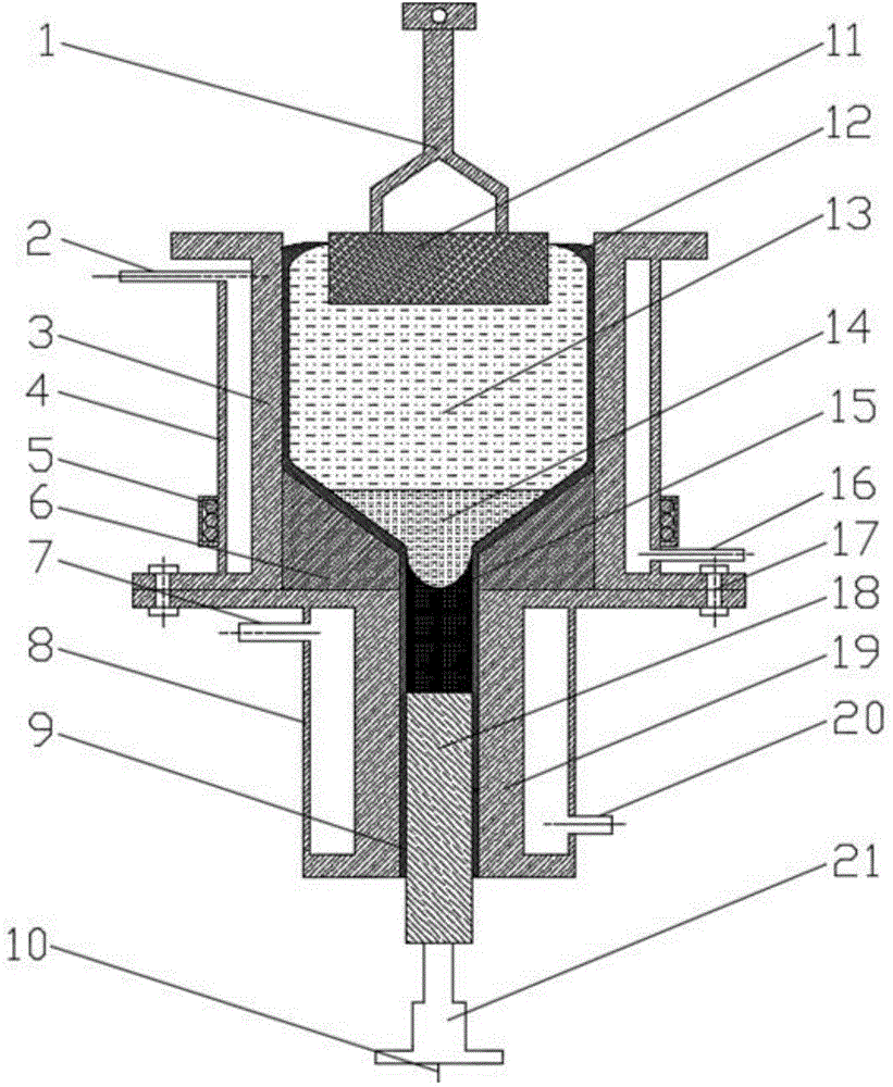
[0024] As shown in the drawings, the electrolytic furnace of the present invention has a diameter D=600mm and a height of 800mm, and is placed on the ingot casting furnace. Before power on, open the cooling water valves of the upper and lower parts of the equipment at the same time, the cooling water flow rate is 30L / h, and place the dummy rod tungsten rod in the ingot cavity of the ingot casting furnace as the cathode. The pre-melted molten salt electrolyte (NdF 3 : LiF=9:0.9) is poured into the hearth of the electrolytic furnace, the cuboid graphite anode with a length of 450mm, a width of 450mm, and a height of 300mm is inserted into the molten salt electrolyte of the hearth of the electrolytic furnace, and the automatic lifting and feeding device of the carbon anode is opened. At a temperature of 1100°C, turn on the power supply for constant current electrolysis, and the anode current density is 0.9A / cm 2In the process of electrolysis, about 5.5Kg of neodymium oxide is ad...

Embodiment 2

[0028] As shown in the drawings, the electrolytic furnace of the present invention has a diameter D=600mm and a height of 800mm, and is placed on the ingot casting furnace. Before power on, open the cooling water valves of the upper and lower parts of the equipment at the same time, the cooling water flow rate is 30L / h, and place the dummy rod tungsten rod in the ingot cavity of the ingot casting furnace as the cathode. Pour the pre-melted molten salt electrolyte (LaF3:LiF=9:1) into the hearth of the electrolytic furnace, insert a cuboid graphite anode with a length of 450 mm, a width of 450 mm, and a height of 300 mm into the molten salt electrolyte in the hearth of the electrolytic furnace, Turn on the carbon anode automatic lifting and feeding device, and at a temperature of 1000°C, turn on the power supply for constant current electrolysis, and the anode current density is 0.8A / cm 2 In the process of electrolysis, about 5.2Kg of lanthanum oxide is added directly to the ano...

Embodiment 3

[0032] As shown in the drawings, the electrolytic furnace of the present invention has a diameter D=600mm and a height of 800mm, and is placed on the ingot casting furnace. Before power on, open the cooling water valves of the upper and lower parts of the equipment at the same time, the cooling water flow rate is 35L / h, and place the dummy rod tungsten rod in the ingot cavity of the ingot casting furnace as the cathode. Pour the pre-melted molten salt electrolyte (PrF3:LiF=9:1.2) into the hearth of the electrolytic furnace, insert a cuboid graphite anode with a length of 450 mm, a width of 450 mm, and a height of 300 mm into the molten salt electrolyte in the hearth of the electrolytic furnace, Turn on the carbon anode automatic lifting and feeding device, and at a temperature of 1100°C, turn on the power supply for constant current electrolysis, and the anode current density is 1A / cm 2 In the process of electrolysis, about 5.5Kg of praseodymium oxide is added directly to the ...


PUM

PropertyMeasurementUnit
diameteraaaaaaaaaa
heightaaaaaaaaaa
heightaaaaaaaaaa

Abstract

The invention relates to a method and a device for preparing rare-earth metal through lower cathode electrolysis and in-situ ingot casting synchronization. The device comprises an electrolysis furnace and an ingot casting furnace which are arranged on a machine frame, wherein a carbon anode is hung at a hearth opening of the electrolysis furnace through an anode conducting rod and is communicated with a positive electrode of a power supply; the anode conducting rod is fixedly arranged on an automatic ascending and descending feeding device arranged on the machine frame; the lower part of a hearth of the electrolysis furnace is provided with a funnel-shaped insulation inner liner; an upper cooling water jacket is arranged outside the furnace wall of the electrolysis furnace; the lower part of the outer side of the upper cooling water jacket is provided with an electromagnetic stirring device; an ingot casting cavity is arranged on the ingot casting furnace; the ingot casting cavity is centered with an outlet of the funnel-shaped insulation inner liner; the lower part of the ingot casting cavity is provided with a sliding ingot guide rod in a matched way; the bottom of the ingot guide rod is connected with an ingot drawing rod and is communicated with the cathode of the power supply through a conducting wire; a lower cooling water jacket is arranged outside the furnace wall of the ingot casting furnace. Constant-voltage or constant-current electrolysis is carried out under the conditions that the temperature is 900 to 1200 DEG C, the voltage is 5 to 30V, and the current is 1000 to 10000A. The rare-earth metal can be continuously and automatically prepared.

Description

technical field [0001] The invention belongs to the field of electrolytic production of rare earth metals, and specifically relates to a method and a device for synchronously and continuously producing rare earth metals integrating "lower cathode electrolysis - magnetic stirring - in-situ casting - automatic ingot extraction out of the furnace". Background technique [0002] At present, there are two main development directions in the large-scale production process of the electrolytic cell type: the first type of electrolytic cell still uses the open-type upward insertion cathode and anode mode designed in the 1980s in terms of electrode configuration, that is, the cathode is separated from the cell body. The outside is vertically inserted into the electrolyte, and the distance between the anode and the cathode is fixed; the second type of electrolytic cell is a model in which someone proposes to use the liquid rare earth metal in the electrolysis process as the cathode for t...

Claims


Application Information

Patent Timeline
Patent Type & Authority Applications(China)
IPC IPC(8): C25C3/34C25C7/00
CPCC25C3/34C25C7/00
Inventor 刘庆生汤卫东江小华
Owner JIANGXI UNIV OF SCI & TECH
Why Eureka
Try Eureka