

A kind of preparation method of field emission flat panel display device of graphene oxide
A flat panel display and field emission technology, applied in the field of nanomaterials, can solve the problems of increasing the complexity of the driving circuit, poor electron emission uniformity, and low electron emission efficiency, and achieve high field enhancement factor, low open electric field, and reduced contact resistance. Effect
- Summary
- Abstract
- Description
- Claims
- Application Information
AI Technical Summary
Problems solved by technology
Method used
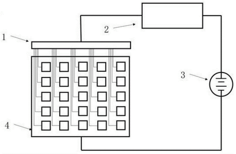
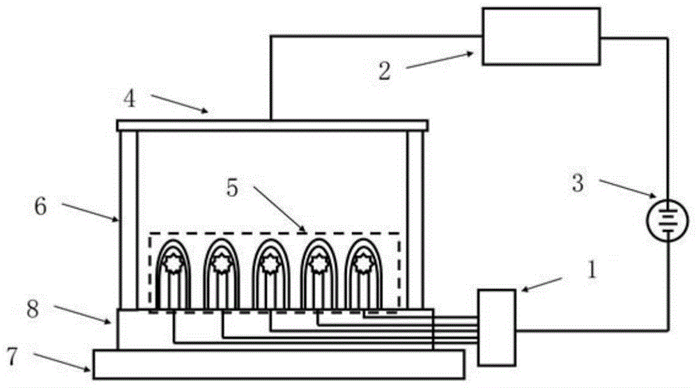
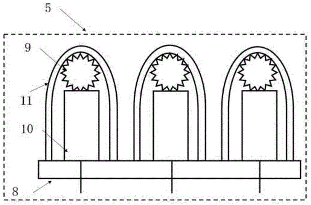
Image

Examples
Embodiment 1
[0023] Step 1, coating a 5 micron thick bis-azide photoresist on the glass.
[0024] Step 2, covering the bis-azide photoresist with a mask plate with a distance of 0.5 micron between dots and an area of each dot of 0.1 square micron. Baking the film at 200°C for 30 minutes; exposing for 20s, developing for 23s; dripping dimethyl sulfoxide on the emission point area, ultrasonication, removing part of the bis-azide photoresist, and exposing the area where the field emission point needs to be prepared.
[0025] Step 3, metal Ti is plated by magnetron sputtering. The specific sputtering conditions are: background vacuum degree 4×10 -4 Pa, argon working pressure 3×10 -1 Pa, sink sputtering power 200W, product rate 20nm / min, sputtering time 20min, Ti thickness 300nm.
[0026] Step 4, magnetic field-assisted precipitation of nickel nanoparticles on the metal film; 100 mg of nickel nanoparticles with an average diameter of 800 nm and 100 ml of ethylene glycol, ultrasonically dis...
Embodiment 2
[0036] In step one, a 5 micron thick phenolic resin photoresist is coated on the silicon.
[0037] Step 2: Cover the phenolic resin photoresist with a distance of 50 microns between dots and a mask plate with an area of 100 square microns, bake the film at 200°C for 30 minutes; expose for 20s, develop for 23s; Dimethyl sulfoxide is dripped on the dot area, and part of the photoresist is removed by ultrasonication, exposing the area where field emission dots need to be prepared.
[0038] Step 3, metal W is plated by magnetron sputtering. The specific sputtering conditions are: background vacuum degree 5×10 -4 Pa, argon working pressure 5×10⁻¹ Pa, sink sputtering power 200W, product rate 20nm / min, sputtering time 13min, W thickness 250nm.
[0039] Step 4, magnetic field-assisted precipitation of nickel nanoparticles on the metal film; 100 mg of nickel nanoparticles with an average diameter of 800 nm and 100 ml of ethylene glycol, ultrasonically dispersed to prepare a suspens...
Embodiment 3
[0047] Step 1, coating 5 micron thick ion beam glue on the polytetrafluoroethylene.
[0048] Step 2: Cover the ion beam gel with a dot-to-dot spacing of 500 microns, each dot has an area of 10,000 square microns mask, bake the film at 200°C for 30 minutes; expose for 20s, develop for 23s; drop on the emission point area Apply dimethyl sulfoxide, ultrasonic, remove part of the photoresist, and expose the area where field emission points need to be prepared.
[0049] Step 3, metal Pd is plated by magnetron sputtering. The specific sputtering conditions are: background vacuum degree 5×10 -4 Pa, argon working pressure 5×10 -1 Pa, sink sputtering power 200W, product rate 20nm / min, sputtering time 13min, Pd thickness 250nm.
[0050] Step 4, magnetic field-assisted precipitation of nickel nanoparticles on the metal film; 200 mg of nickel nanoparticles with an average diameter of 800 nm and 100 ml of ethylene glycol, ultrasonically dispersed to prepare a suspension. Put the samp...
PUM
| Property | Measurement | Unit |
|---|---|---|
| thickness | aaaaa | aaaaa |
| thickness | aaaaa | aaaaa |
| thickness | aaaaa | aaaaa |
Abstract
Description
Claims
Application Information