Low energy consumption water-air separation device and method

A technology of air separation and low energy consumption, applied in separation methods, dispersed particle separation, chemical instruments and methods, etc., can solve the problems of harsh operating conditions, low operating temperature, high pressure, etc., achieve moderate hydration conditions, good effect, and improve efficiency Effect

Active Publication Date: 2015-08-19
SOUTH CHINA UNIV OF TECH
View PDF6 Cites 12 Cited by
  • Summary
  • Abstract
  • Description
  • Claims
  • Application Information

AI Technical Summary

Problems solved by technology

The main problems are that the operating temperature is low, the p

Method used


Image

  • Low energy consumption water-air separation device and method
  • Low energy consumption water-air separation device and method

Examples


Embodiment 1

[0043] Example 1: Single-stage continuous hydration separation of air

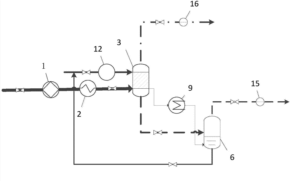
[0044] Such as figure 1 As shown, a low-energy hydration air separation device includes a compressor 1, a precooling system 2, a first hydration tower 3, a first decomposition tower 6, a first heat pump 9, a first vacuum pump 12, and a first oxygen concentration detection Device 15 and the second oxygen concentration detector 16; Compressor 1 and precooling system 2 are connected by pipeline, and precooling system 2 communicates with the air inlet of the first hydration tower 3, and the liquid inlet of the first hydration tower 3 connects the first Vacuum pump 12, the hydrate solution output port of the first hydration tower 3 is connected with the feed port of the first decomposition tower 6, the raffinate output port of the first decomposition tower 6 is connected with the liquid inlet of the first hydration tower 3, the first hydration Tower 3 and the first decomposition tower 6 are also connected by t...

Embodiment 2

[0054] Embodiment 2: single-stage continuous hydration separation air (see figure 1 )

[0055] A kind of hydration air separation method comprises the steps:

[0056] 1) Clean the first hydration tower 3 and the first decomposition tower 6. The first hydration tower 3 and the first decomposing tower 6 are vacuumized, and the hydration accelerator and distilled water are added to the liquid inlet of the first hydration tower 3 by the first vacuum pump 12. The hydration accelerator is tetrabutylammonium fluoride TBAF (thermodynamically promoted agent) mass fraction x=0.35, sodium dodecyl sulfate SDS (kinetic accelerator) mass fraction x=0.05, distilled water is 500ml.

[0057] 2) The raw material is air (a binary mixed gas of 21mol% oxygen and 79mol% nitrogen), and the air enters the first hydration tower 3 for hydration, and controls the temperature t of the compressed air entering the first hydration tower 3 1 =32°C, pressure p 1 = 42.5 MPa. After the hydrate is formed, t...

Embodiment 3

[0060] Embodiment 3: single-stage batch hydration separation air (see figure 1 )

[0061] A method for separating hydrated air, comprising the steps of:

[0062] 1) Clean the first hydration tower 3 and the first decomposition tower 6. The first hydration tower 3 and the first decomposition tower 6 are vacuumized, and the hydration accelerator and distilled water are added to the liquid inlet of the first hydration tower 3 by the first vacuum pump 12. The hydration accelerator is tetrahydrofuran THF (thermodynamic accelerator) mass fraction x =0.165, distilled water is 500ml, operating conditions are:

[0063] 1) The raw material is air (a binary mixed gas of 21mol% oxygen and 79mol% nitrogen), and the air enters the first hydration tower 3 for hydration, and controls the temperature t of the compressed air entering the first hydration tower 3 1 =-0.5℃, pressure p 1 = 3.5 MPa. After the hydrate is formed (by increasing the gas-liquid mass transfer contact area, such as st...


PUM


Abstract

The invention discloses a low energy consumption water-air separation device and method. The device comprises a compressor, a pre-cooling system and at least one hydration tower, one decomposition tower, one vacuum pump and one heating pump; the compressor and the pre-cooling system are connected through a pipeline, the pre-cooling system is communicated with the air inlet of a first hydration tower, the liquid inlet of the first hydration tower is connected to a first vacuum pump, the hydrate liquid outlet of the first hydration tower is connected to the feed port of the first decomposition tower, the residual liquid outlet of the first decomposition tower is connected to the liquid inlet of the first hydration tower, the first hydration tower and the first decomposition tower are connected through a first heating pump, the upper portion of the first hydration tower is provided with a gas release recovery port, and the upper portion of the first decomposition tower is provided with an oxygen-enriched air release and recovery port. The air is separated according to the principle that hydration of oxygen and water is performed more easily as compared with that of nitrogen and water, the hydration pressure is lowered by adding hydration accelerator, the pressure difference for oxygen generating hydrate is larger than that for nitrogen, and the energy consumption can be reduced by more than 30%.

Description

technical field [0001] The invention relates to the field of air separation, in particular to a hydration air separation device and method capable of operating at low pressure and low energy consumption. Background technique [0002] Air is a mixed gas mainly composed of oxygen and nitrogen. In nature, a large amount of air exists in the air in a free state. The air with an oxygen concentration greater than 20.95 mol% is called oxygen-enriched air, and the air with a nitrogen concentration greater than 79.05 mol% is called nitrogen-enriched air. [0003] Nitrogen is mainly used for ammonia synthesis, protective atmosphere for metal heat treatment, inert protective gas in chemical production (pipeline purge when starting and stopping, nitrogen seal for easily oxidized substances, pressing materials), grain storage, fruit preservation and electronic industry, etc. Oxygen is mainly used as an oxidant in metallurgy, gas-supporting, medical treatment, wastewater treatment and ch...

Claims


Application Information

Patent Timeline
IPC IPC(8): B01D53/00C01B13/02C01B21/02
CPCY02P20/129
Inventor 樊栓狮龙小军郎雪梅王燕鸿
Owner SOUTH CHINA UNIV OF TECH
Why Eureka
Try Eureka