Manufacture technique of tap shells for polar drill rigs

A faucet shell and manufacturing process technology, which is applied to the driving device for drilling in the borehole, earthwork drilling and production, drilling equipment, etc., can solve the problems of low pass rate, high reject rate, small operating space, etc., and achieve economical and simple. Effect of high strength and improved reliability

Inactive Publication Date: 2015-09-30
RG PETRO MACHINERY GROUP
View PDF5 Cites 13 Cited by
  • Summary
  • Abstract
  • Description
  • Claims
  • Application Information

AI Technical Summary

Problems solved by technology

[0009]The faucet shell with cast structure has two disadvantages: one is that the impact energy can only reach the impact energy at -45℃ required by GB / T19190 and API Spec Specification 8C , the impact energy at -60°C is difficult to achieve, and the performance stability is poor, and the pass rate is low; the second is that the casting process has a high probability of defects, magnetic particle inspection and ultrasonic flaw detection are often unqualified, the scrap rate is high, and the first pass rate is only 30-60%, poor reliability
[0010]The main body of the welded faucet shell is purely welded between plates, and the weld seam becomes a weak link, and the heat-affected zone and weld seam cannot meet GB / T19190 and API The impact force at -60°C required by Spec Specification 8C is because the plate is thicker, the operating space is small, and the internal welding is difficult. The non-destructive testing of the weld is not easy to implement because of the shape of the shell and the thickness of the plate, and welding defects become an influence The main factor of product quality, and the thick plates currently available on the market can only guarantee the impact energy at -40°C

Method used


Image

  • Manufacture technique of tap shells for polar drill rigs
  • Manufacture technique of tap shells for polar drill rigs
  • Manufacture technique of tap shells for polar drill rigs

Examples


Embodiment 1

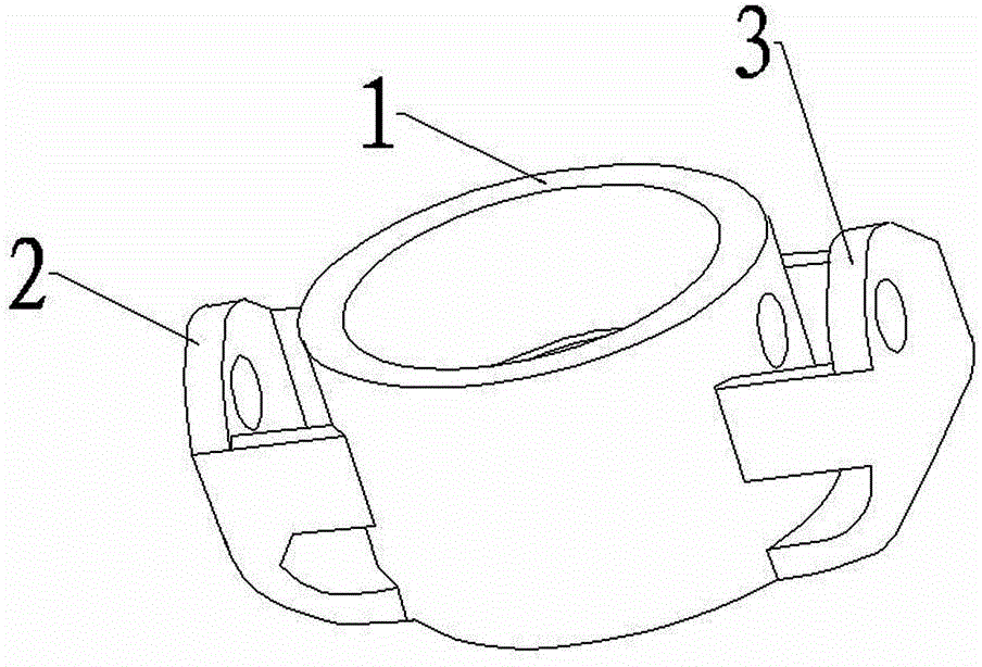
[0043] Example 1: Design and manufacturing process of the faucet shell for the ZJ15 polar drilling rig.

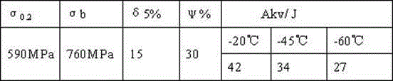
[0044] 1) Design description: use the engineering machinery design software solidworks to carry out the molding process design of the faucet shell, and determine the process dimensions of the shell body and the ear plate; specifically, the rated load is 1100KN, and the minimum service temperature is -60 ℃, calculated by design, see the shape figure 1 , outer diameter 404mm, inner diameter 326mm, housing pin hole inner diameter 70mm, safety factor 3.20, material 35CrMoA, mechanical performance requirements: σ0.2≥590MPa, σb≥780MPa, δ5≥15%, ψ≥30%, Akv (-20 ℃) ≥ 42J, Akv (-60 ℃) ≥ 27J, according to GB / T19190 and API Spec Specification 8C for magnetic particle testing and ultrasonic testing.

[0045] 2) Cutting material: Ф250х649mm round steel; cutting according to the principle that the size ratio is not less than 3, the material block I corresponding to the main body of the ...


PUM


Abstract

The invention discloses a manufacture technique of tap shells for polar drill rigs. The manufacture technique incudes: (1) for forging, performing forging via upsetting, punching, broaching and forming to guarantee a forging fiber flow line under the conditions that heating temperature is 1270-1310 DEG C, initial forging temperature is 1100-1250 DEG C and terminal temperature is not lower than 850 DEG C, performing annealing after forging under the condition that the heating temperature is 880+/-20 DEG C, and performing furnace cooling to enable tapping temperature not higher than 300 DEG C; (2) for heat treatment, normalizing at temperature of 880-900 DEG C prior to air cooling, quenching at temperature of 840-860 DEG C prior to oil cooling or cooling with a PAG quenching medium, tempering at temperature of 580+/-40 DEG C prior to air cooling, performing subcritical quenching at temperature of 790+/-10 DEG C prior to oil cooling or cooling with the PAG quenching medium, and tempering at temperature of 520-600 DEG C prior to air cooling; (3) for non-destructive inspection, finishing prior to machining a product according to size, and performing ultrasonic inspection and magnetic particle inspection, wherein the qualified level conforms to API Specification 8C standards. Compared with the prior art, the manufacture technique has the advantages that the tap shells manufactured with the technique have high strength to guarantee enough safety factor, adapt to polar regions (at the temperature of minus 60 DEG C) and meet the requirement on enough low temperature impact toughness so as to resist to the low-temperature environment of the polar regions.

Description

technical field [0001] The invention belongs to the technical field of oil drilling rig equipment manufacturing, and in particular relates to a manufacturing process for a water tap shell of an polar drilling rig. Background technique [0002] The proven oil reserves in the Arctic region account for about 1 / 4 of the world's total. As the world's energy demand continues to grow, oil exploration, development, and oil production continue to shift to the polar environment. Oil drilling rigs, as essential equipment, require Serving in a low temperature environment (-60°C), the faucet is a key component on the main load path, and its function is to introduce drilling fluid and bear the load of the drill string and drilling tools, requiring high reliability. The API Specification 8C of the American Petroleum Institute and its equivalent Chinese national standard GB / T19190 have put forward very high requirements for it, not only requiring high strength, but also enough to ensure tha...

Claims


Application Information

Patent Timeline
Patent Type & Authority Applications(China)
IPC IPC(8): B23P15/00C21D1/18C21D8/00
CPCB23P15/00C21D1/19C21D8/00E21B4/00
Inventor 赵旭平张正芳张宸李书旭赵志周王东
Owner RG PETRO MACHINERY GROUP
Why Eureka
Try Eureka