
A high-concentration saline organic waste liquid incineration boiler

A high-concentration salt-containing and organic waste liquid technology is applied in the field of high-concentration chemical salt-containing organic waste liquid incineration boilers and high-concentration salt-containing organic waste liquid incineration boilers. Problems such as blockage can be avoided, and the manufacturing process is simple, the processing cost is reduced, and the maintenance is convenient.

Active Publication Date: 2017-11-07
大连科林能源工程技术开发有限公司
View PDF5 Cites 6 Cited by
  • Summary
  • Abstract
  • Description
  • Claims
  • Application Information

AI Technical Summary

Problems solved by technology

[0004] Patent CN103047659A proposes an incineration process and an incineration boiler for treating high-concentration salt-containing organic waste liquid, including a downward adiabatic furnace, a multi-stage radiation cooling chamber, a convective heat exchange chamber, a soot blowing device, a steam-water outlet pipe and a steam drum. The waste liquid incineration boiler described in the patent has the following disadvantages: (1) The volume of the downward adiabatic furnace is too large from top to bottom. In order to ensure the combustion temperature of the furnace, a large amount of auxiliary fuel must be consumed, which increases the cost of waste liquid treatment; (2) Between the descending adiabatic furnace and the first radiant cooling chamber, a number of vertical and inclined deflectors are arranged, which can easily cause the vertical and inclined deflectors to be blocked by molten inorganic salts in the flue gas after incineration , causing the device to malfunction
(3) There is no folding smoke wall between the downward adiabatic furnace and the first radiant cooling chamber, and the opening of the downward adiabatic furnace is turned to the first radiative cooling chamber. Due to the effect of heat radiation, the first radiant cooling chamber has a significant impact on the incineration of the downward adiabatic furnace. Negative effect, it is difficult to make the incineration of the downward adiabatic furnace reach the point of high temperature combustion, unless a large amount of auxiliary fuel is consumed to ensure the incineration temperature of the downward adiabatic furnace, if the consumption of auxiliary fuel is increased, the flue gas volume will increase, and the flue gas flow rate will increase accordingly This will not only cause the tail temperature to be too high, but what is even more harmful is that the increase in the flue gas flow rate will cause the flue gas to take away a large amount of molten salt to the rear multi-stage radiation cooling chamber, resulting in serious salt accumulation in the multi-stage radiation cooling chamber, which endangers safety. reliable operation
If the consumption of auxiliary fuel is not increased, it will be difficult to ensure the temperature of the lower part of the downward adiabatic furnace, and it will be difficult to discharge slag in liquid state, and even cause the slag discharge outlet to be blocked and unable to discharge slag; (4) There is no heating surface in the multi-stage radiation cooling chamber. The physical characteristics of molten salt can only be solid particles with less adhesion when the temperature of the molten salt is much lower than the melting point of the molten salt, but the flue gas carries a large number of fine molten salt particles, which will adhere to the multi-stage The radiant cooling chamber, especially the furnace wall surface of the first few stages of radiative cooling chamber, causes the heating surface of the multi-stage radiative cooling chamber to stick to dirt, which affects the radiative cooling efficiency, and causes the blockage of the multi-stage radiative cooling chamber and the ash hopper at the bottom of the multi-stage radiative cooling chamber is damaged. Molten salt is clogged and cannot work properly
On the other hand, molten salt sticks to the heating surface of the radiation cooling chamber, which leads to weakened radiation heat transfer and reduces the efficiency of waste heat recovery, resulting in a large incineration boiler and increased construction investment; (5) The incineration boiler only arranges convection pipes for longitudinal flushing in the low temperature area screen, the heat transfer effect is very poor, resulting in high exhaust gas temperature and low boiler thermal efficiency
(6) An open liquid slag discharge device is installed on the right side of the lower part of the downward adiabatic furnace. This liquid slag discharge device is difficult to operate reliably. The less viscous the salt is, but the structural characteristics of the device determine that the temperature of the descending adiabatic furnace is difficult to be much higher than the melting point of the molten salt, so the auxiliary fuel consumption must be increased during operation to increase the temperature of the descending adiabatic furnace to meet the requirements of liquid slag discharge. requirements; on the other hand, the exposed liquid slag discharge device radiates heat to the atmosphere. This process is very rapid, so that the molten salt easily adheres to the pipeline of the liquid slag discharge device due to cooling, and begins to partially block, and gradually the entire liquid discharge The slag device cannot operate normally

Method used


Image

  • A high-concentration saline organic waste liquid incineration boiler
  • A high-concentration saline organic waste liquid incineration boiler
  • A high-concentration saline organic waste liquid incineration boiler

Examples


Embodiment

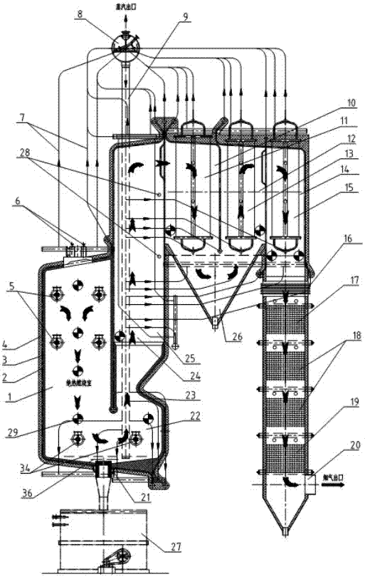
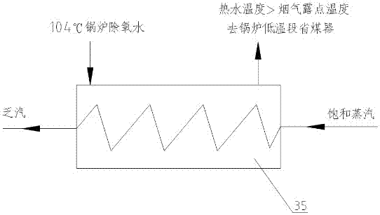
[0022] Such as figure 1 A high-concentration chemical industry salt-containing organic waste liquid incineration boiler is shown, and the arrow direction indicates the direction of high-temperature flue gas from waste liquid incineration; its structure mainly includes: adiabatic combustion chamber (1), adiabatic combustion steering chamber ( 22), adiabatic combustion steering chamber smoke shielding wall (23), quenching chamber (24), quenching membrane wall tube panel (25), convection cooling chamber I (10), convection evaporation tube panel I (11), convection cooling chamber II (12), Convection Evaporation Panel II (13), Convection Cooling Chamber III (14), Convection Evaporation Panel III (15), Expansion Joint (16), High Temperature Section Economizer (17), Medium Temperature Section Economizer (18), low-temperature section economizer (19), boiler flue gas outlet (20), molten salt cooling tank (27), molten salt reheating burner (34), feed water preheater (35).

[0023] The ...


PUM


Abstract

The invention discloses an incineration boiler for high-concentration salty organic waste liquid. The environment-friendly and energy-saving requirements for harmlessness, reduction and resourcezation of high-concentration salty organic waste liquid are met through high-temperature incineration and waste heat recovery. The incineration boiler structurally and mainly comprises auxiliary combustors, waste liquid spray guns, a thermal insulation hearth combustion chamber, a steering chamber, a radiation cooling chamber, a radiation water-cooling pipe panel, convection current evaporation pipe panels, a steam pocket, a high-temperature economizer, a low-temperature economizer, an ash falling bucket, a flue connection expansion joint and a furnace wall. The thermal insulation hearth combustion chamber is formed by a hearth wall-covering film type water-cooling wall in a defined manner, salty waste liquid is combusted, and recycling is conducted in a salt dissolving tank. High-temperature smoke generated in combustion sequentially enters the thermal insulation combustion steering chamber, a quenching chamber, the multiple stages of convection current evaporation cooling chambers and the economizers to be subjected to heat energy recovery. The incineration boiler has the beneficial effects of being simple in manufacturing process, convenient to maintain, safe and stable in running, and suitable for being used and popularized in high-concentration salty organic waste liquid processing in the industries of chemical engineering, oil refining, papermaking and the like.

Description

technical field [0001] The invention relates to an environmental protection and energy-saving equipment for incinerating high-concentration salt-containing organic waste liquid in chemical industry and papermaking industry and recovering heat energy, in particular to an incineration boiler for high-concentration chemical salt-containing organic waste liquid. The invention relates to an environment-friendly and energy-saving equipment for incinerating high-concentration salt-containing organic waste liquid in chemical industry, oil refining and papermaking industries and recovering heat energy, in particular to a high-concentration salt-containing organic waste liquid incineration boiler. Background technique [0002] In recent years, with the rapid development of chemical industry, oil refining, papermaking and other industries, a large amount of high-concentration chemical and salt-containing organic waste liquid is often produced in the production process. These waste liqui...

Claims


Application Information

Patent Timeline
Patent Type & Authority Patents(China)
IPC IPC(8): F23G7/04F22B1/18F22D1/32
CPCY02P20/10
Inventor 余传林何成国唐义磊王祺李鹏飞郑贺曹红阳曹威
Owner 大连科林能源工程技术开发有限公司
Learn More