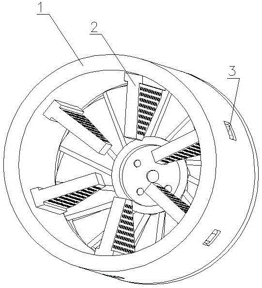
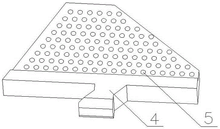
Ceramic methanol fuel pyrolyzer for stove
A technology of methanol fuel and cracker, which is applied in the direction of heating fuel, liquid heating fuel, application, etc., can solve the problem of low efficiency of methanol cracker, and achieve the effect of improving thermal shock resistance, high hardness, and increasing temperature
- Summary
- Abstract
- Description
- Claims
- Application Information
AI Technical Summary
Problems solved by technology
Method used
Image
Examples
Embodiment 1
[0016] Example 1 8 kilograms of magnesium oxide, 6 kilograms of aluminum oxide, 7 kilograms of niobium oxide, 15 kilograms of feldspar, 4 kilograms of zirconia powder, 9 kilograms of glycerol, 8 kilograms of clay, 7 kilograms of hydroxypropyl methylcellulose, toluene 4 kg of diisocyanate, 5 kg of wood fiber, 4 kg of chromium oxide, 6 kg of diatomaceous earth, 4 kg of mixed solution of potassium oxide and sodium oxide, 12 kg of aluminum clay, 3 kg of iron red, 7 kg of limestone, and 6 kg of nano-iron oxide kg, 6 kg of silicone resin, 0.2 kg of cyclohexanone, 0.3 kg of chlorinated paraffin, and 1 kg of polyethylene glycol. The fixed material is crushed to 80 mesh, added with 30 kg of water, soaked for 12 hours, then formed, dried for 10 hours under shading conditions, fired in a kiln for 10 hours, and the kiln temperature is 1100-1150 degrees.
Embodiment 2
[0017] Embodiment 2 Magnesia 16 kilograms, aluminum oxide 5 kilograms, niobium oxide 11 kilograms, feldspar 10 kilograms, zirconia powder 7 kilograms, glycerol 6 kilograms, clay 10 kilograms, hydroxypropyl methylcellulose 5 kilograms, toluene 10 kg of diisocyanate, 3 kg of wood fiber, 6 kg of chromium oxide, 3 kg of diatomaceous earth, 7 kg of mixed solution of potassium oxide and sodium oxide, 7 kg of aluminum clay, 6 kg of iron red, 5 kg of limestone, and 8 kg of nano-iron oxide kg, 4 kg of silicone resin, 0.4 kg of cyclohexanone, 0.1 kg of chlorinated paraffin, and 2 kg of polyethylene glycol. The fixed ceramic raw material was pulverized to 50 mesh, added 35 kg of water, and dried for 8 hours under sunshade conditions. The preparation method was the same as in Example 1.
Embodiment 3
[0018] Example 3 10 kilograms of magnesium oxide, 5 kilograms of aluminum oxide, 9 kilograms of niobium oxide, 13 kilograms of feldspar, 5 powders of zirconia powder, 8 kilograms of glycerol, 9 kilograms of clay, 6 kilograms of hydroxypropyl methylcellulose, toluene 7 kg of diisocyanate, 4 kg of wood fiber, 5 kg of chromium oxide, 4 kg of diatomaceous earth, 5 kg of mixed solution of potassium oxide and sodium oxide, 10 kg of aluminum clay, 5 kg of iron red, 6 kg of limestone, and 7 kg of nano-iron oxide kg, 5 kg of silicone resin, 0.3 kg of cyclohexanone, 0.2 kg of chlorinated paraffin, and 1 kg of polyethylene glycol. The solid ceramic raw material is pulverized to 70 meshes, and the amount of water added is 25 kilograms. The preparation method is the same as in Example 1.
PUM
| Property | Measurement | Unit |
|---|---|---|
| pore size | aaaaa | aaaaa |
Abstract
Description
Claims
Application Information
 - R&D
- Intellectual Property
- Life Sciences
- Materials
- Tech Scout
- Unparalleled Data Quality
- Higher Quality Content
- 60% Fewer Hallucinations
Browse by: Latest US Patents, China's latest patents, Technical Efficacy Thesaurus, Application Domain, Technology Topic, Popular Technical Reports.
© 2025 PatSnap. All rights reserved.Legal|Privacy policy|Modern Slavery Act Transparency Statement|Sitemap|About US| Contact US: help@patsnap.com


