Coal-sludge co-combustion system based on high-temperature smoke drying and pneumatic conveying

A high-temperature flue gas and pneumatic conveying technology, used in dehydration/drying/concentrated sludge treatment, combustion methods, combustion equipment, etc., can solve the problems of complex system process, poor sealing performance of belt conveying system, and large floor space. To achieve the effect of system simplicity

Active Publication Date: 2016-01-27
UNIV OF SHANGHAI FOR SCI & TECH
View PDF7 Cites 13 Cited by
  • Summary
  • Abstract
  • Description
  • Claims
  • Application Information

AI Technical Summary

Problems solved by technology

This leads to complex system process, many equipments, large floor area and high investment cost; and because the dried sludge will emit dust and odor during the stacking and transportation process, and the sealing performance of the belt conveying system is poor, Therefore, it is easy to cause odor to spread in the factory area and nearby areas, resulting in a bad working environment and seriously affecting the enthusiasm of the power plant for incinerating sludge.
At present, there is also a sludge flue gas drying-pulverized coal boiler co-firing process scheme based on the fan mill pulverization system, but the gas-powder mixture produced during the process of drying the sludge in the fan mill and grinding it into powder has a strong The irritating smell, corrosiveness and high dust concentration make it difficult to separate the gas and powder, and the explosion-proof requirements are relatively high, so there is no engineering application yet.

Method used


Image

  • Coal-sludge co-combustion system based on high-temperature smoke drying and pneumatic conveying

Examples


Embodiment Construction

[0018] The present invention will be further described below in conjunction with the accompanying drawings and embodiments.

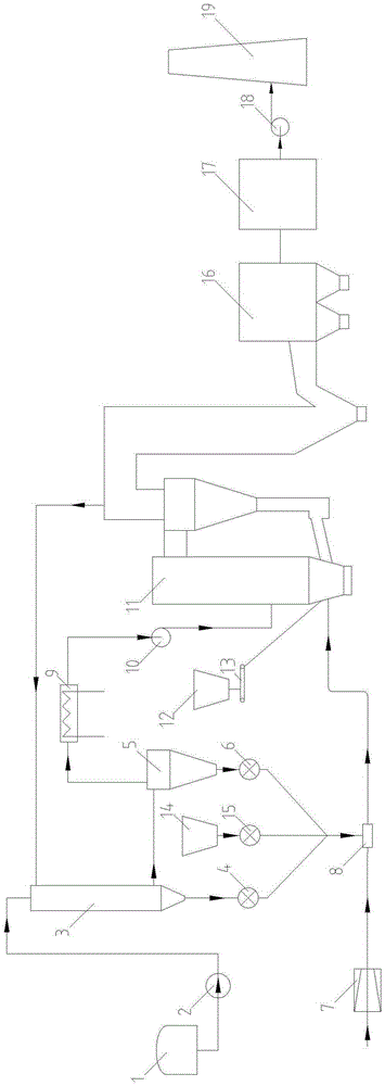
[0019] Such as figure 1 As shown, the coal-sludge co-combustion system based on high-temperature flue gas drying and pneumatic conveying of the present invention includes a sludge storage bin 1, a screw pump 2, a spray drying pipe 3, a rotary feeder-4, and a cyclone separator 5. Rotary feeder 2 6. Roots blower 7. Jet feeder 8. Cooling condenser 9. Exhaust air fan 10. Circulating fluidized bed boiler 11. Coal hopper 12. Coal feeder 13. Limestone bin 14 , Rotary feeder three 15, dust collector 16, desulfurization device 17, induced draft fan 18 and chimney 19.

[0020] The outlet of coal feeder 12 is connected to coal feeder 13, the outlet of coal feeder 13 is connected to circulating fluidized bed boiler 11, and the outlet of circulating fluidized bed boiler 11 is connected to dust collector 16, desulfurization device 17, induced draft fan 18, chimney ...


PUM


Abstract

The invention relates to a coal-sludge co-combustion system based on high-temperature smoke drying and pneumatic conveying. A sludge storage bin is connected with a spray drying pipe through a screw pump. An air inlet of the spray drying pipe is connected with a cyclone separator outlet flue of a circulating fluidized bed boiler. A first outlet of the spray drying pipe is connected with a first rotary feeder, and a second outlet of the spray drying pipe is connected with a cyclone separator. An exhaust opening of the cyclone separator is connected with the circulating fluidized bed boiler through a cooling condenser and an exhaust gas fan, and a discharging opening of the cyclone separator is connected with a second rotary feeder. A limestone bin is connected with a third rotary feeder. An outlet of the first rotary feeder, an outlet of the second rotary feeder and an outlet of the third rotary feeder are connected with a feeding opening of a jet feeding device, an air inlet of the jet feeding device is connected with a Roots fan, and an outlet of the jet feeding device is connected with the circulating fluidized bed boiler. The functions of sludge drying and conveying, dry tail gas waste heat utilization, sludge and coal co-combustion, pollutant control and the like can be achieved, bad smell and dust diffusion can be avoided, and the coal-sludge co-combustion system has the beneficial effects of being simple, environment-friendly and efficient.

Description

technical field [0001] The invention relates to a waste disposal system, in particular to a system for drying sludge and co-firing with coal. Background technique [0002] With the increasing amount of urban sewage generation and treatment, the sludge produced in the process of urban sewage treatment is also increasing day by day. Sludge is a floc composed of water, organic particles and inorganic particles, which contains a large amount of heavy metals, pathogens and refractory toxic organic substances, and emits odor. Therefore, sludge must be properly disposed of. [0003] Sludge pretreatment includes conditioning, concentration, dehydration, stabilization, and drying technologies. The final disposal of sludge mainly includes landfill, land use, construction material utilization, biological treatment, and incineration. Pyrolysis, gasification, and Emerging technologies such as thermal hydrolysis are also being researched and developed. Due to the increasing requirement...

Claims


Application Information

Patent Timeline
Patent Type & Authority Applications(China)
IPC IPC(8): F23K3/00F23K1/00C02F11/12B01D53/83B01D53/50B01D45/12
Inventor 王波陈翀施大钟郑晓园闻哲马睿
Owner UNIV OF SHANGHAI FOR SCI & TECH
Why Eureka
Try Eureka