Microbial fuel reactor and battery applying same

A microbial fuel and fuel cell technology, applied in the field of reactors, can solve the problems of a large number of unfavorable microorganisms attached, narrow catalytic performance, small anode surface area, etc., to ensure proton conductivity, improve proton conductivity and energy efficiency, and catalyze good performance

Inactive Publication Date: 2016-02-24
CHENGDU 90 DEGREE IND PROD DESIGN CO LTD
View PDF2 Cites 2 Cited by
  • Summary
  • Abstract
  • Description
  • Claims
  • Application Information

AI Technical Summary

Problems solved by technology

However, the existing microbial fuel cells generally have the disadvantage of low electricity production; at the same time, the surface area of ​​the anode in the prior art is generally small, which is not conducive to the attachment of a large number of microorganisms, and the catalytic performance is narrow; in the prior art, platinum is mostly used as Cathodic catalyst, although the catalytic effect is good, but too expensive

Method used


Image

  • Microbial fuel reactor and battery applying same
  • Microbial fuel reactor and battery applying same
  • Microbial fuel reactor and battery applying same

Examples


Embodiment 1

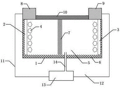
[0041] Such as Figure 1 to Figure 4 As shown, a microbial fuel reactor includes a sealed shell 6 and an anode 2 and a negative electrode 3 arranged in the sealed shell 6, microorganisms 4 are attached to the surface of the anode 2 and the negative electrode 3, and an ion exchange is provided between the anode 2 and the negative electrode 3 Membrane 7, anode 2 is connected to battery positive pole 8, cathode 3 is connected to battery negative pole 9, sealed shell 6 is filled with medium 5; anode 2 is surface titanium / nitrogen doped mesoporous graphene airgel, cathode 3 is VO2 / S - AC foam nickel air cathode; microorganism 4 is Shewanella putrefaciens, medium 5 is trimethylamine p-oxide.

[0042] Ion membrane exchange membrane 7 comprises perfluorosulfonic acid proton membrane one, and the lower layer of perfluorosulfonic acid proton membrane one is covered with silicon dioxide layer, and the lower layer of silicon dioxide is covered with perfluorosulfonic acid proton membrane t...

Embodiment 2

[0045] Anode 2 is prepared through the following steps:

[0046] Step 1: Add graphite powder and sodium nitrate to the concentrated sulfuric acid at the mass ratio of concentrated sulfuric acid: graphite powder: sodium nitrate 65:1:0.6 in an ice bath, stir and dissolve for 30 minutes, and then add graphite powder: potassium permanganate according to the mass ratio of graphite powder: potassium permanganate Ratio 1:5, add potassium permanganate to the mixed solution, stir for 10 hours, add deionized water to the mixed solution according to the volume ratio of concentrated sulfuric acid: deionized water 1:1, and place the mixture under the condition of a vacuum degree of 0.93 Slowly raise the temperature to 52°C at a rate of 1.2°C / h, keep stirring at a constant temperature of 52°C for 22 hours, then add hydrogen peroxide to the mixed solution according to the volume ratio of concentrated sulfuric acid to hydrogen peroxide (1:0.1), and stir at 52°C for 2.5 hours Centrifuge, separ...

Embodiment 3

[0049] Cathode 3 is made by the following steps:

[0050] Step 1: According to the mass ratio of 1:1, mix polyvinyl alcohol and polytetrafluoroethylene evenly to prepare a catalytic emulsion with a concentration of 10%, and mix VO 2 Mix evenly with S-AC according to the mass ratio of 2:1, and weigh VO according to the mass ratio of 1:3 2 / S-AC mixture and catalytic emulsion, the VO 2 / S-AC mixture and catalytic emulsion were mixed ultrasonically for 40 minutes, the mixed solution was heated to 65°C, and stirred continuously for 2 hours to break the emulsion to obtain the raw material of the catalytic layer;

[0051] Step 2: Press the nickel foam into a 0.6mm sheet by a tablet press, and evenly scrape the raw material of the catalytic layer on the upper surface of the foam nickel, and then microwave it for 5 minutes under the condition of a pressure of 70kPa and a power of 100W, and the surface of the sheet The excess powder is gently swept away to obtain foamed nickel covere...


PUM

PropertyMeasurementUnit
Thicknessaaaaaaaaaa
Aperture sizeaaaaaaaaaa
Thicknessaaaaaaaaaa

Abstract

The invention discloses a microbial fuel reactor and belongs to the field of reactors. The microbial fuel reactor comprises a seal shell and an anode and a cathode arranged in the seal shell, microorganisms adhere to the surface of the anode and the surface of the cathode, an ion exchange membrane is arranged between the anode and the cathode, the anode is connected with a positive pole of a battery, the cathode is connected with a negative pole of the battery, and the seal shell is filled with media; the anode is made of surface titanium / nitrogen doped mesoporous graphene aerogel, and the cathode is a VO<2> / S-AC foamed nickel air cathode; the microorganisms are shewanella putrefaciens, and the media are p-trimethylamine oxide. The microbial fuel reactor has the advantages that the electrode surface activation area is large, electrostatic interaction between the microorganisms and the electrode surface is increased, adsorbability of the microorganisms is enhanced, catalytic performance is good, thereby the electricity output is raised, and production cost is lowered.

Description

technical field [0001] The invention relates to a reactor, in particular to a microbial fuel reactor. Background technique [0002] As the world's population continues to increase, human beings are increasingly affected by insufficient energy resources and environmental degradation. Therefore, the development of new energy sources has been widely valued, and the use of renewable biomass energy for power generation is an effective means. Microbial fuel cells (MFC), as a new method of using microbial metabolism to generate electricity, has attracted more and more attention in recent years. It is a device that uses microorganisms as catalysts to convert chemical energy into electrical energy. Microorganisms can metabolize organic substances and generate electrical energy at the same time. However, the existing microbial fuel cells generally have the disadvantage of low electricity production; at the same time, the surface area of ​​the anode in the prior art is generally small...

Claims


Application Information

Patent Timeline
IPC IPC(8): H01M8/16H01M8/0258H01M4/86H01M4/90
CPCH01M4/86H01M4/90H01M8/02H01M8/0289H01M8/16Y02E60/50
Inventor 曾丽
Owner CHENGDU 90 DEGREE IND PROD DESIGN CO LTD
Why Eureka
Try Eureka