Pollution gas treatment system and treatment method

A technology for polluting gas and treatment systems, applied in the direction of gas treatment, separation methods, chemical instruments and methods, etc., to achieve stable operation, high selectivity, and easy operation

Inactive Publication Date: 2016-03-30
UNIV OF SCI & TECH BEIJING +1
View PDF8 Cites 7 Cited by
  • Summary
  • Abstract
  • Description
  • Claims
  • Application Information

AI Technical Summary

Problems solved by technology

[0005] The main purpose of the present invention is to provide a treatment system and method for polluted gas. The technical problem to be solved is to use the principle of chemical looping combustion to process polluted gas so that no oxygen carrier will appear during the process. Sulfur poisoning, no NO formation x , the process conditions are easy to control, so it is more suitable for practical

Method used


Image

  • Pollution gas treatment system and treatment method
  • Pollution gas treatment system and treatment method
  • Pollution gas treatment system and treatment method

Examples


Embodiment 1

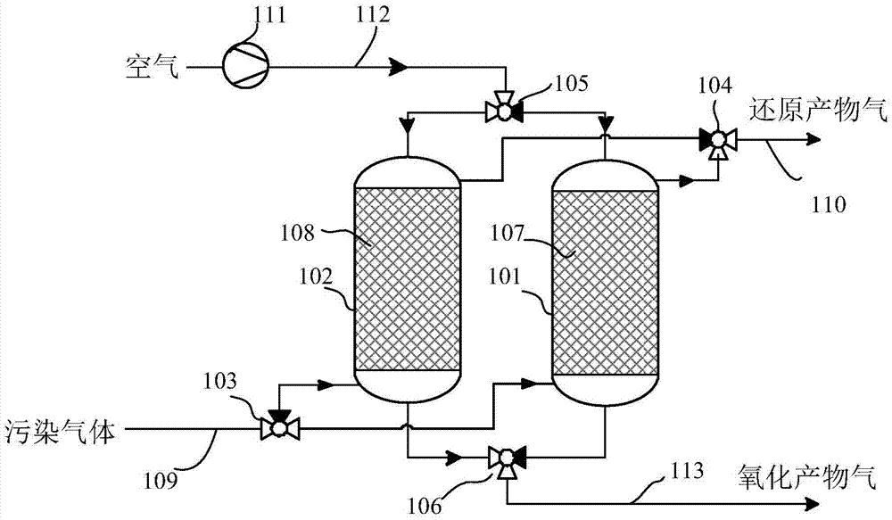
[0033] Please refer to figure 1 . The pollution gas treatment system shown includes: the first chemical looping combustion reactor 101 filled with the oxidation state 107 of the copper-based oxygen carrier, and the second chemical looping combustion reactor filled with the reduced state 108 of the copper-based oxygen carrier 102. Pollution gas pipeline 109, air blower 111, air pipeline 112, reduction reaction product gas pipeline 110, oxidation reaction product gas pipeline 113, and electric three-way valve groups 103-106. The active substance of the copper-based oxygen carrier is CuO, and the carrier is SiO 2. The polluting gas contains NH 3 .

[0034] The polluted gas enters the first chemical looping combustion reactor 101 through the three-way valve 103 on the polluted gas pipeline 109, and undergoes a reduction reaction with the oxidized oxygen carrier 107: the NH in the polluted gas 3 React with the oxidized oxygen carrier 107 to generate nitrogen and water vapor, w...

Embodiment 2

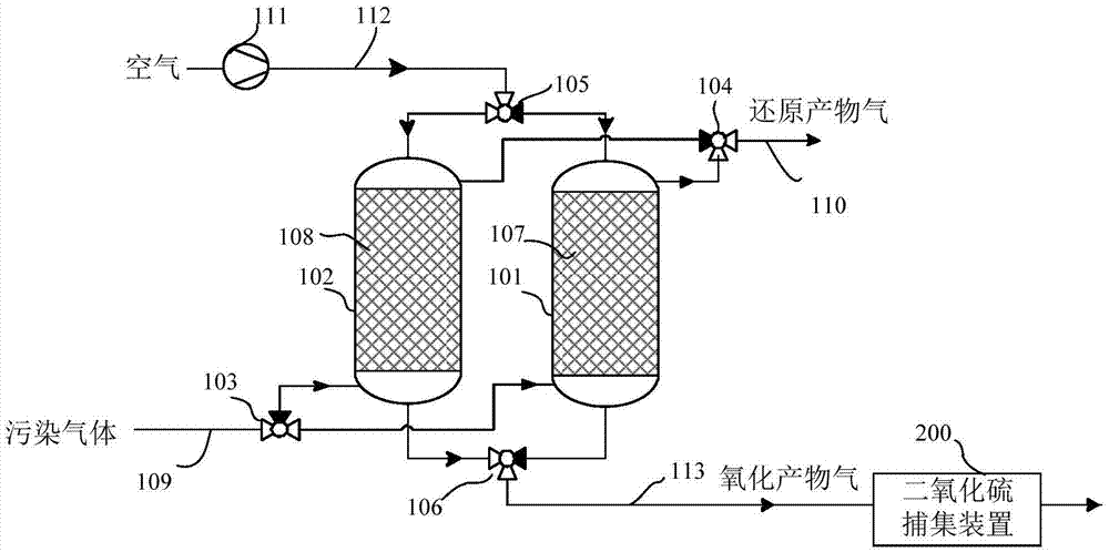
[0043] Please refer to figure 2 . Compared with Example 1, this embodiment differs in that: the oxygen carrier is an iron-based oxygen carrier, and its active material is Fe 2 o 3 , the carrier is Al 2 o 3 . The temperature of reduction reaction and oxidation reaction is 300°C. A sulfur dioxide capture device 200 is arranged on the oxidation reaction product gas pipeline 113 to capture SO in the oxidation reaction product gas 2 , the sulfur dioxide capture device 200 is a wet desulfurization device using limestone or lime slurry as a desulfurizing agent. Pollution gas contains trimethylamine and H 2 S.

[0044] Oxidation states of iron-based oxygen carriers with trimethylamine and H 2 The reduction reaction of S, and the reduced state and iron sulfide with O 2 The reaction equation of the oxidation regeneration reaction and the standard free energy change and reaction heat at the reaction temperature are as follows:

[0045] 63Fe 2 o 3 +2C 3 h 9 N(g)=42Fe 3 o ...

Embodiment 3

[0053] Please refer to figure 2 . Compared with Example 2, this embodiment differs in that: the oxygen carrier is a nickel-based oxygen carrier, its active material is NiO, and the carrier is TiO 2 . The temperature of the reduction reaction and the oxidation reaction is 350°C, and a sulfur dioxide capture device 200 is installed on the oxidation reaction product gas pipeline 113 to capture SO in the oxidation reaction product gas 2 , the sulfur dioxide trapping device 200 is a dry desulfurization device using calcium oxide as a desulfurizing agent. The polluting gas contains methyl mercaptan and toluene.

[0054] Reduction reactions of the oxidized state of nickel-based oxygen carriers with methyl mercaptan and toluene, and the reduced state and nickel sulfide with O 2 The reaction equation of the oxidation regeneration reaction and the standard free energy change and reaction heat at the reaction temperature are as follows:

[0055] 4NiO+CH 3 SH(g)=NiS+3Ni+CO 2 +2H ...


PUM


Abstract

The invention relates to a pollution gas treatment system and treatment method based on a chemical looping combustion principle; the pollution gas treatment system includes a first chemical looping combustion reactor, a second chemical looping combustion reactor, gas pipelines and three-way valves; the chemical looping combustion reactors are filled with oxygen carriers; the gas pipelines include a pollution gas pipeline, an air pipeline, a reduction reaction product gas pipeline and an oxidation reaction product gas pipeline; pollution gas contains hydrogen sulfide and other sulfur compounds or ammonia, trimethylamine and other amines. The treatment method includes the following steps: the pollution gas and the oxidation-state oxygen carrier undergo a reduction reaction, oxygen and the reduction-state oxygen carrier or metal sulfides undergo an oxidizing regeneration reaction, when the gas concentration in the two chemical looping combustion reactors reaches a set value, the three-way valves are switched, and treatment goes into a next cycle. The oxygen carriers with suitable oxidation ability are selected, in the process of pollution gas treatment, NOx is not generated, SO2 can be captured, the treatment conditions are easy to control, and the device and the method are more suitable for practical application.

Description

technical field [0001] The invention relates to a gas treatment system, in particular to a treatment system and method for polluted gas based on the principle of chemical loop combustion. Background technique [0002] In people's daily production and life, many polluting gases will be produced, such as waste gas from industrial production, waste gas from spraying workshops, and odor from landfills. There are many types of harmful components in these waste gases, mainly including H 2 S, sulfur compounds such as methyl mercaptan, NH 3 And amines such as trimethylamine and butylenediamine, various volatile organic compounds (VOCs) gases such as "triphenyl" and formaldehyde, etc. These polluting gases will bother the lives of nearby residents, and also cause adverse effects on the environment such as photochemical smog, acid rain, and greenhouse effect. Therefore, the research and development of efficient polluting gas treatment systems has always been a research hotspot. [0...

Claims


Application Information

Patent Timeline
Patent Type & Authority Applications(China)
IPC IPC(8): B01D53/75B01D53/82B01D53/80B01D53/60
CPCB01D53/60B01D53/75B01D53/80B01D53/82B01D2251/20B01D2251/602B01D2251/606B01D2257/302B01D2257/40B01D2257/406Y02A50/20
Inventor 苏庆泉武永健
Owner UNIV OF SCI & TECH BEIJING
Why Eureka
Try Eureka