Denitration catalytic performance evaluation system and method

A denitrification catalyst and evaluation system technology, applied in the field of denitrification catalyst performance evaluation system, can solve the problems affecting unit economy, reliability and continuity, low-temperature operation performance attenuation, air preheater clogging and dust accumulation, etc., and the evaluation method is simple Reliability, improved applicability, reduced pollution effect

Inactive Publication Date: 2016-04-20
STATE GRID HEBEI ENERGY TECH SERVICE CO LTD
View PDF17 Cites 14 Cited by
  • Summary
  • Abstract
  • Description
  • Claims
  • Application Information

AI Technical Summary

Problems solved by technology

At present, problems such as excessive ammonia escape, accelerated deactivation of catalysts, high-temperature sintering of catalysts, attenuation of low-temperature operation performance, and dust a

Method used


Image

  • Denitration catalytic performance evaluation system and method
  • Denitration catalytic performance evaluation system and method
  • Denitration catalytic performance evaluation system and method

Examples


Embodiment 1

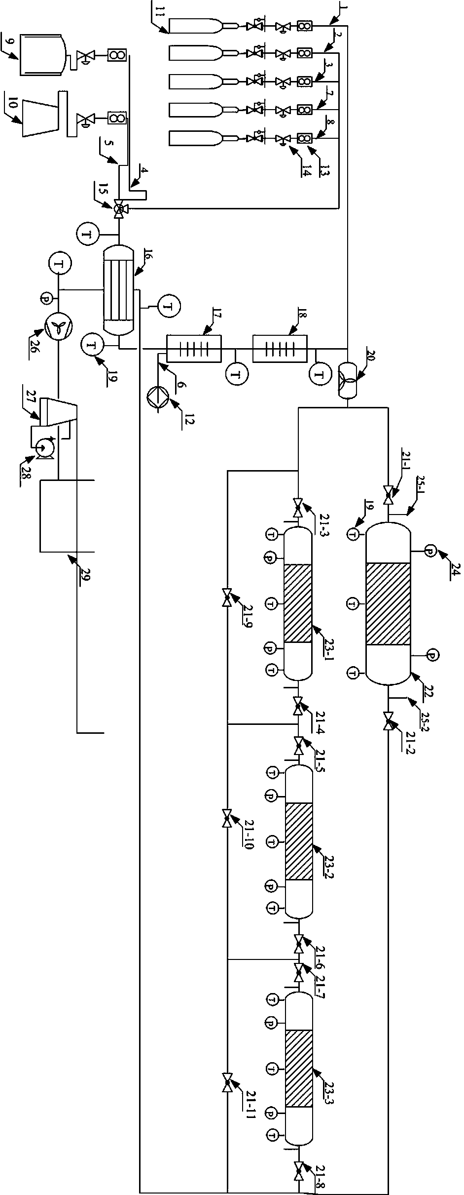
[0028] Such as figure 1 As shown, a denitrification catalyst performance evaluation system, including gas metering system, gas preheating system, SCR catalytic reaction system, gas-gas heat exchanger, tail gas treatment system and control system.

[0029] The denitrification catalyst performance evaluation system is provided with 8 air inlets, respectively NH 3 Inlet 1, SO 2Air inlet 2, NO inlet 3, first backup gas inlet 7, second backup gas inlet 8, nitrogen inlet 4, air inlet 5, water vapor inlet 6, where N 2 Produced by nitrogen production unit 9, O 2 The content is regulated by air compressor 10 introducing air 5, NH 3 , SO 2 , NO, the first backup gas, and the second backup gas use the steel cylinder 11 gas, and the water vapor 6 uses the flow-adjustable metering injection pump 12 to add water and generate through heating.

[0030] NH 3 , SO 2 , NO, N 2 Gas mass flowmeters 13 are installed on each gas pipeline such as air, first standby gas, and second standby gas...

Embodiment 2

[0075] Other steps are identical with embodiment 1, and g step can be replaced by following steps: close valve 21-1, valve 21-2, valve 21-5~valve 21-8, open valve 21-9~valve 21-11, valve 21- 3. The valve 21-4 allows the flue gas flowing out of the mixing device 20 to pass through the second reactor 23-1 and connect the flue gas analyzer to the front sampling port 25-1 and the rear sampling port 25-1 of the second reactor 23-1. 2, Pass the test SO 2 , NO, NO 2 , CO 2 , SO 3 and NH 3 The flue gas concentration of the second reactor 23-1 can be used to obtain the ammonia nitrogen molar ratio, denitrification efficiency, ammonia slip rate and SO 2 / SO 3 Conversion rates.

Embodiment 3

[0077] Other steps are identical with embodiment 1, and g step can be replaced by following steps: close valve 21-1, valve 21-2, valve 21-9~valve 21-11 of the first reactor, open valve 21-3~valve 21- 8. Let the flue gas flowing out of the mixing device 20 pass through the second reactor 23-1, the third reactor 23-2 and the fourth reactor 23-3 in series, and connect the flue gas analyzer to the second reactor 23 -1 front sampling port 25-1 and the fourth reactor 23-3 rear sampling port 25-2, by testing SO 2 , NO, NO 2 , CO 2 , SO 3 and NH 3 The concentration of flue gas can be used to obtain the ammonia nitrogen molar ratio, denitrification efficiency, ammonia slip rate and SO 2 / SO 3 Conversion rates.


PUM


Abstract

The invention relates to a denitration catalytic performance evaluation system and method. The evaluation system comprises a distributed gas metering system, a gas preheating system, an SCR system, a gas-gas heat exchanger (16), a tail gas treatment system and a data collection and control system. Through the system and method, the ammonia-nitrogen molar ratio, denitration efficiency, the ammonia escape rate, activity and the SO2/SO3 conversion rate of reactor catalysts can be obtained. The system has complete functions, is accurate and reliable in operation and can be widely applied to evaluation of catalytic performance on laboratory conditions.

Description

technical field [0001] The invention relates to the field of flue gas denitration, in particular to a denitrification catalyst performance evaluation system and an evaluation method thereof. Background technique [0002] Nitrogen oxides (NOx) are one of the main flue gas pollutants in thermal power plants. A large amount of emissions will not only cause acid rain and photochemical smog, but also cause great harm to human health. According to the "Emission of Air Pollutants from Thermal Power Plants" (GB13223-2011), the NOx concentration of coal-fired power plants will be 100mg / Nm 3 emission limits. According to this requirement, selective catalytic reduction (selective catalytic reduction, SCR) technology with high denitrification efficiency, mature technology and no secondary pollution has gradually become the mainstream of flue gas denitrification process. [0003] The denitration catalyst is the core part of the denitration device and belongs to the "loss" part. There ...

Claims


Application Information

Patent Timeline
IPC IPC(8): G01N33/00
CPCG01N33/00
Inventor 陈崇明李振海宋国升候海萍郁金星
Owner STATE GRID HEBEI ENERGY TECH SERVICE CO LTD
Why Eureka
Try Eureka