Calcium carbide waste heat recycling method and recycling system

A waste heat recovery and calcium carbide technology, which is applied in the field of energy saving and emission reduction, can solve the problems of no calcium carbide waste heat utilization method and practical technology, uneven center heat and edge of calcium carbide pot, and unusable heat in the center of calcium carbide pot, etc., to achieve simple heat utilization method , Avoid broken problems, high energy saving effect

Inactive Publication Date: 2016-05-18
盐城远洋节能科技有限公司
View PDF11 Cites 4 Cited by
  • Summary
  • Abstract
  • Description
  • Claims
  • Application Information

AI Technical Summary

Problems solved by technology

Calcium carbide process consumes 1100kg / t of standard coal and 3400Kw of electricity per hour. Calcium carbide produced in a closed calcium carbide furnace at 2200°C contains high heat, which can account for 21% of the overall energy consumption. 231kg / t standard coal. At the end of the “Thirteenth Five-Year Plan”, the production capacity of calcium carbide will be controlled at 50 million t / a, and the waste heat will reach 11.55 million t / a standard coal. At present, there is no method and method for utilizing calcium carbide waste heat in actual projects. practical technology
[0003] The current patents for the utilization of calcium carbide waste heat are as follows: Calcium carbide furnace-based 
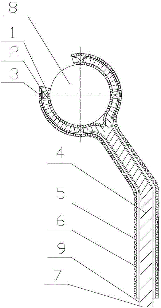
sensible heat power generation system and its realization method (application number 201410238546.0). This patent provides a ring-shaped heat exchange system around the calcium carbide furnace. The heat exchanger is a heat conduction heat utilization method with low efficiency. For a heat exchanger with a high temperature of 2200°C, existing materials cannot be used in engineering applications; The sensible heat collection system includes a calcium carbide liquid collection and storage device, a high-temperature-resistant heat insulation plate matching the top opening of the calcium carbide liquid collection and storage device, a superconducting heat exchange device connected to the calcium carbide liquid collection and storage device at one end, and an evaporator at the other end, It is located at the top of the evaporator and is used to discharge the steam-water mixture. The cavity of the calcium carbide liquid collection and storage device is composed of an inner wall and an outer wall that has a gap with the inner wall and forms a sealed structure. The inner and outer wall gaps of the calcium carbide liquid collection and storage device Arranged with seamless steel pipes, the interior of the seamless steel pipes is filled with a heat-conducting medium. This patent is also a thermal energy utilization method of heat conduction; a calcium carbide furnace calcium carbide sensible heat recovery equipment and recovery method (application number 201410040367.6) mainly includes calcium carbide laundering, smoking Cover, hot air tunnel kiln, transport out track, high temperature cyclone dust collector, waste heat boiler, bag filter, high temperature induced draft fan and automatic control system. This patent is also a heat utilization method of heat convection, and the convection heat transfer efficiency is low, and Dust removal and other equipment and problems have been added; a calcium carbide sensible heat collection device (application number 201420344707.X) includes a closed heat collection box. The two side walls and a ceiling at the top of the two side walls, the bottom surface, the side walls and the ceiling together form a storage space for storing calcium carbide pot cars. The wall and the ceiling include a steel cylinder, a phase change heat storage material filled in the steel cylinder and an insulation layer covering the outer surface of the top of the steel cylinder. The outlet end of the hot box is provided with an air outlet, and the air inlet is used to flow in cold air
In the calcium carbide sensible heat collection device, the heat of the calcium carbide on the calcium carbide pot car is conducted to the phase-change heat storage material through the steel cylinder, and the cold air flowing in from the air inlet is heated during the process of flowing through the gap of the phase-change heat storage material. It is a hot air flow, which flows out from the air outlet to be sent to the equipment that needs heat energy for recycling. This patent can only recover waste heat at the bottom of the calcium carbide pot, and transfer heat through heat conduction and convection. The efficiency is low. In addition, the center of the calcium carbide pot The heat and the edge are not uniform, so that the heat in the center of the calcium carbide pot cannot be used; a fused calcium carbide power generation system (application number 201420550583.0), the energy conversion equipment includes a hot blast stove (21), a waste heat boiler (22), and a circulating fan (23); A circulating air outlet (211) is provided on the end of the hot blast stove close to the sealed chamber, and a circulating air inlet (212) is provided at the end far away from the sealed chamber; The air inlet is connected to the circulating fan; the waste heat boiler and the circulating fan are connected through the ventilation pipe (25); related patents or applications also include a calcium carbide furnace calcium carbide sensible heat recovery device (CN201410040368.0), a calcium carbide furnace calcium carbide Sensible heat recovery device (CN201420053876.8), a calcium carbide sensible heat recovery device (CN201120489712.6), a calcium carbide sensible heat recovery system (CN201120209958.3), the above patents or applications are combined with the existing calcium carbide pot The traditional convective heat transfer method cannot eliminate the technical problems existing in combination with existing calcium carbide pots, warehouses, and crushed material processes, and it is difficult to achieve engineering and simple docking with existing devices

Method used


Image

  • Calcium carbide waste heat recycling method and recycling system
  • Calcium carbide waste heat recycling method and recycling system
  • Calcium carbide waste heat recycling method and recycling system

Examples


Embodiment Construction

[0028] Such as figure 1 As shown, the present invention includes a closed tunnel 6, a calcium carbide feeding system 4 and a water-cooled wall system 5, the calcium carbide feeding system 4 and the water-cooled wall system 5 are located in the tunnel 6, the calcium carbide feeding system discharge port 7 and the calcium carbide material warehouse (not shown in the figure) output) or equipment connection in other follow-up processes, in order to facilitate the discharge of calcium carbide feeding system 4, the discharge port 7 of the calcium carbide feeding system extends out of the tunnel 6; 5 is arranged around the heat transfer protection tube 9; at the feed end of the calcium carbide feeding system 4, a calcium carbide discharge collection system 2 is provided. Then it enters the calcium carbide feeding system 4; since the calcium carbide is not continuously released from the furnace, it can be continuously fed to the calcium carbide feeding system through the collection of...


PUM


Abstract

The invention provides a calcium carbide waste heat recycling method. Calcium carbide is discharged from a calcium carbide furnace, the temperature of the calcium carbide can reach about 2200 DEG C, and the calcium carbide carries high thermal energy. According to the method, calcium carbide waste heat is recycled in radiation and convective heat transfer modes. A calcium carbide discharge and collection system, a closed tunnel, a calcium carbide feeding system and a water-cooling wall system are involved. After calcium carbide materials are discharged out of the furnace, the calcium carbide materials are continuously conveyed through the calcium carbide discharge and collection system and fed to the calcium carbide feeding system, the whole calcium carbide discharge and collection system and the calcium carbide feeding system are located in the closed tunnel, and the water-cooling wall system is disposed in the tunnel. Heat of the calcium carbide materials is recycled through water circulation, and the heat is converted into steam energy through a water-cooling wall and cooling media in a pipe of the water-cooling wall to be used for power generation or technologies. In the calcium carbide cooling process, solidification of a calcium carbide boiler ingot can be avoided. Meanwhile, a waste heat collecting method is simple, process equipment saves energy and is simple, investment is low, the energy-saving effect is high, and produced steam can be used for power generation or other uses.

Description

technical field [0001] The invention relates to a calcium carbide waste heat recycling method and a calcium carbide waste heat recycling system, which are suitable for utilization of calcium carbide material cooling waste heat in the calcium carbide industry, and belong to the technical field of energy saving and emission reduction. Background technique [0002] Electricity and carbon materials account for a large proportion of the cost of calcium carbide products, about 70%. From 2000 to 2010, domestic calcium carbide production capacity increased from 4.8 million t / a to 22.5 million t / a, and output increased from 3.4 million t / a Since the "Twelfth Five-Year Plan", a large number of calcium carbide projects supporting large-scale chlor-alkali installations have been launched. By the end of 2012, there were 388 domestic calcium carbide enterprises, with a production capacity of 32.3 million t / a and an increase of output to 20 million t / a, the production capacity of the close...

Claims


Application Information

Patent Timeline
Patent Type & Authority Applications(China)
IPC IPC(8): F27D17/00
CPCY02P10/25
Inventor 葛京鹏葛霖王和勇罗才志
Owner 盐城远洋节能科技有限公司
Why Eureka
Try Eureka