
Sintering flue gas synchronous desulfurization and denitration process based on optical-electric type fenton coupling regeneration

A technology for sintering flue gas, desulfurization and denitrification, applied in gas treatment, membrane technology, dispersed particle separation, etc., can solve the problems of expensive EDTA and cysteine, high cost pressure, etc. The effect of reducing the burden

Inactive Publication Date: 2016-08-10
JIANGSU DISA MACHINERY +1
View PDF5 Cites 4 Cited by
  • Summary
  • Abstract
  • Description
  • Claims
  • Application Information

AI Technical Summary

Problems solved by technology

Although Fe(II)EDTA and ferrous cysteine ​​have shown certain application potential in simultaneous desulfurization and denitrification, due to the high price of EDTA and cysteine, it brings great cost pressure to simultaneous desulfurization and denitrification

Method used


Image

  • Sintering flue gas synchronous desulfurization and denitration process based on optical-electric type fenton coupling regeneration
  • Sintering flue gas synchronous desulfurization and denitration process based on optical-electric type fenton coupling regeneration
  • Sintering flue gas synchronous desulfurization and denitration process based on optical-electric type fenton coupling regeneration

Examples


Embodiment Construction

[0042] Process example:

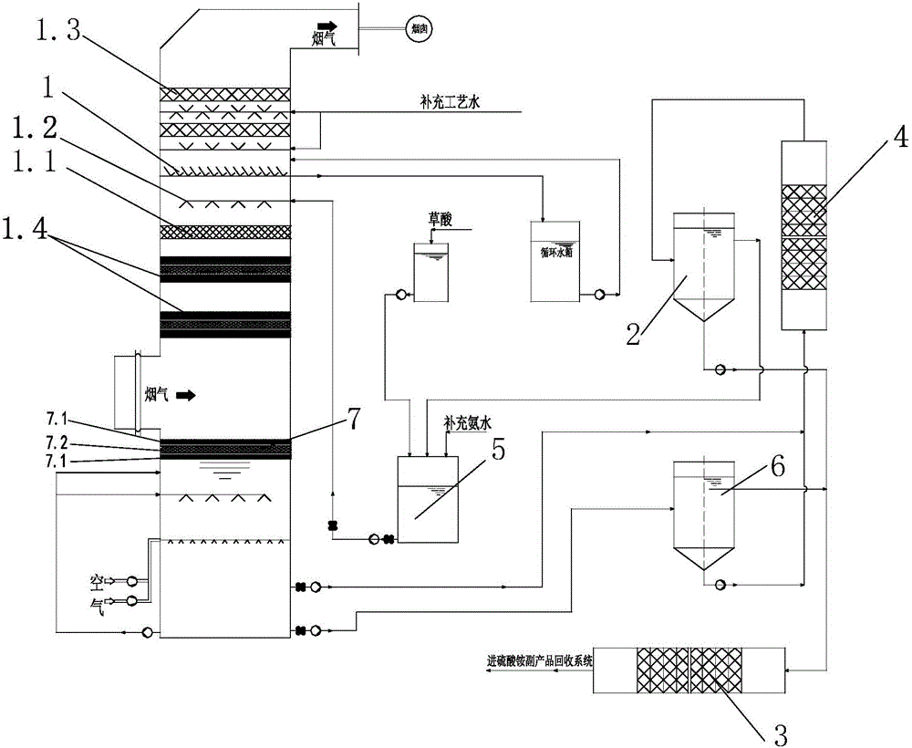
[0043] see figure 1 , in a sintering flue gas desulfurization system, the sintering flue gas volume is about 14-16Nm 3 / h, SO 2 Concentration: 500~800mg / Nm 3 , NOx concentration (mainly NO): 300~400mg / Nm 3 , particulate matter (which contains elemental iron) concentration: 30~50mg / Nm 3 . The desulfurization adopts the ammonia water absorption process in the packed tower.

[0044] The physical parameters and related composition of the absorption liquid are as follows:

[0045] pH value: 5.0~5.5;

[0046] Ammonium sulfate concentration: 20-45% (mass percentage);

[0047] Total concentration of Fe(II)+Fe(III): 0.045~0.15mol / L;

[0048] Concentration of oxalate ion: 0.27~0.9mol / L;

[0049] Absorption liquid temperature: 50-55°C.

[0050] The flue gas is introduced into the middle of the absorption tower 1, and in the absorption tower 1, the flue gas flows from bottom to top through at least one photochemical reaction layer 1.4 (two layers in th...


PUM

PropertyMeasurementUnit
voidageaaaaaaaaaa

Abstract

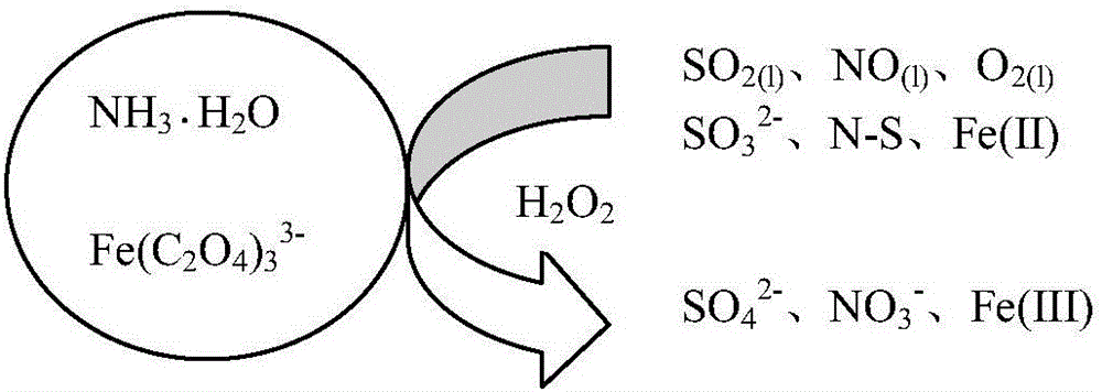
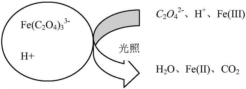
The invention relates to a sintering flue gas synchronous desulfurization and denitration process based on optical-electric type fenton coupling regeneration. The sintering flue gas synchronous desulfurization and denitration process comprises the following steps: flue gas is fed into an absorption tower to have a reverse contact reaction with a circulating absorption solution sprayed out by a spraying layer, and then is discharged out from the top of the absorption tower, specifically, the flue gas enters the absorption tower from a flue gas inlet in the middle of the absorption tower, sequentially passes through at least one photochemical reaction layer, a packing layer and the spraying layer, which are arranged at the upper part of the tower, to have the reverse contact reaction with the circulating absorption solution, and then is discharged out from a flue gas outlet at the top of the absorption tower; after the circulating absorption solution sprayed out by the spraying layer at the upper part of the absorption tower sequentially passes through the packing layer and the at least one photochemical reaction layer to have the reverse contact reaction with the flue gas, the circulating absorption solution is electrolyzed to be regenerated through an electrolysis regeneration layer at the lower part of the absorption tower, and then is conveyed to a photocatalysis regeneration reaction system from the bottom of the absorption tower to be regenerated; and ammonia water and oxalic acid are supplemented into a regenerated slurry groove and then are conveyed back into the spraying layer at the upper part of the absorption tower to be sprayed into the tower. The sintering flue gas synchronous desulfurization and denitration process is simple, and is low in operation cost, good in denitration effect and good in byproduct quality.

Description

technical field [0001] The invention relates to a flue gas ammonia synchronous desulfurization and denitrification process in the field of environmental protection, in particular to a sintering flue gas synchronous desulfurization and denitrification process based on photoelectric fenton coupling regeneration. Background technique [0002] According to statistics from the Ministry of Environmental Protection, SO in the steel industry in 2013 2 , NOx, and smoke (powder) dust emissions were 1.993 million tons, 5.555 million tons, and 619,000 tons, of which SO 2 Emissions accounted for 10.5% of the total emissions from industrial sources, second only to the thermal power industry. The sintering process is the main emission source of these pollutants, SO 2 The emissions of pollutants such as , NOx and particulate matter accounted for more than 85%, 40% and 35% of the total emissions of iron and steel enterprises, so the treatment of sintering flue gas pollutants is the key obj...

Claims


Application Information

Patent Timeline
Patent Type & Authority Applications(China)
IPC IPC(8): B01D53/90B01D53/60B01D53/96
CPCB01D53/007B01D53/8637B01D53/90B01D53/965B01D2251/2062B01D2251/70B01D2258/0283B01D2259/124B01D2259/804
Inventor 韩军吴高明戴汝山
Owner JIANGSU DISA MACHINERY
Learn More