
Under-light conversion layer for silicon solar cell and manufacturing method of under-light conversion layer

A technology of silicon solar cells and conversion layers, applied in the field of solar cells, can solve the problems of small molar absorptivity, low absorption cross-section, and difficulty in obtaining high quantum yield by directly exciting rare earth ions, so as to achieve large molar coefficient of light absorption and reduce Energy loss, effect of improving photoelectric conversion efficiency

Inactive Publication Date: 2016-08-17
CHANGCHUN INST OF TECH
View PDF2 Cites 1 Cited by
  • Summary
  • Abstract
  • Description
  • Claims
  • Application Information

AI Technical Summary

Problems solved by technology

However, the f-f transition of rare earth ions doped in inorganic powder materials and glasses is parity forbidden, and its molar absorptivity is small and the absorption cross section is low, resulting in ineffective photoexcitation and low luminous intensity, and it is difficult to obtain direct excitation of rare earth ions High Quantum Yield Luminescence

Method used


Image

  • Under-light conversion layer for silicon solar cell and manufacturing method of under-light conversion layer

Examples


Embodiment 1

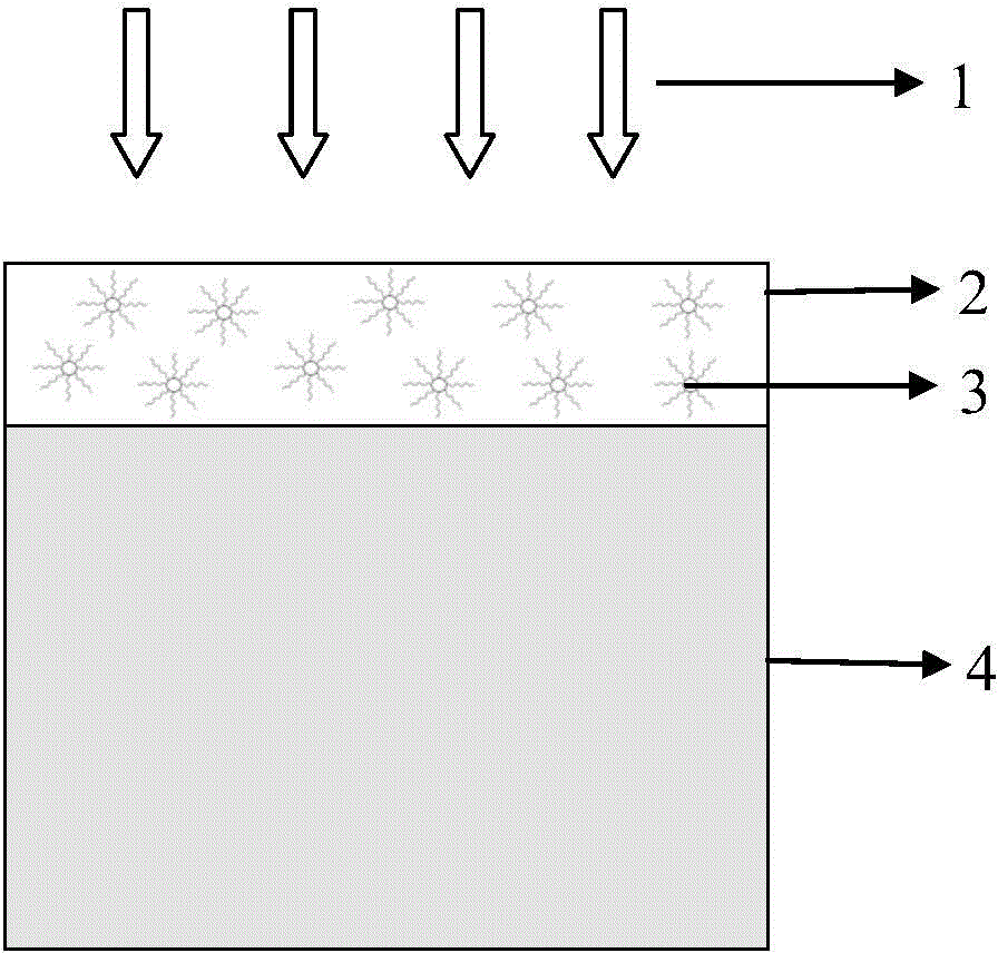
[0018] Example 1: Rare earth organic-inorganic hybrid near-infrared quantum tailoring nanomaterial 5-SSA-NaGdF 4 :1%Tb 3+ ,8Yb 3+ The preparation comprises the following steps:

[0019] (1) Configure 0.2M Gd(NO 3 ) 3 , Tb(NO 3 ) 3 and Yb(NO 3 ) 3 Rare earth nitrate aqueous solution;

[0020] (2) Take by weighing 28mmol trisodium citrate and add deionized water to make 40ml sodium citrate aqueous solution;

[0021] (3) Take 0.2M Gd(NO 3 ) 3 13.16ml, Tb(NO 3 ) 3 0.14ml, Yb(NO 3 ) 3 Add 1.12ml into (2), and stir thoroughly for 40min;

[0022] (4) Add 22ml of 0.4M NaF aqueous solution into (3), and stir thoroughly for 30min;

[0023] (5) Move the mixed solution to a polytetrafluoroethylene reaction kettle, seal it, put it in a vacuum oven, keep it at 180°C for 24h, and then cool it naturally to room temperature;

[0024] (6) Precipitate, centrifuge and wash the reacted solution to obtain NaGdF 4 :1%Tb 3+ ,8Yb 3+ nanomaterials;

[0025] (7) NaGdF will be obtain...

Embodiment 2

[0027] Embodiment 2: the preparation of light conversion layer, flow process is as follows:

[0028] (1) PMMA is added in chloroform and is made into the PMMA chloroform solution that mass percent is 5%;

[0029] (2) 5-SSA-NaGdF 4 :1%Tb 3+ ,8Yb 3+ Added to the above PMMA chloroform solution, 5-SSA-NaGdF 4 :1%Tb 3+ ,8Yb 3+ The mass percentage with PMMA is 5:95, fully stirred for 10 hours to form a colloid, and then left to stand for 12 hours;

[0030](3) Place the silicon solar cell substrate on a spin coater, drop the above-mentioned colloid on the silicon solar cell substrate at a rotation speed of 2000r, keep it for 30s, then remove it and place it in a vacuum drying oven at 25°C for 5h.


PUM


Abstract

The invention relates to an under-light conversion layer for a silicon solar cell and a manufacturing method of the under-light conversion layer. Firstly, a rare earth organic-inorganic hybrid near-infrared quantum cutting nano material is prepared and is evenly dispersed in a transparent polymer, and the under-light conversion layer for a silicon solar cell is prepared by means of a spin-coating method or a dip-coating method. The rare earth organic-inorganic hybrid near-infrared quantum cutting nano material in the conversion layer has a large light absorption molar coefficient and a wide absorption band, comprises an inorganic matrix which protects cations at the luminescence center from luminescence quenching of a non-radiative passivating source, and is compatible with high-molecular polymers. The rare earth organic-inorganic hybrid near-infrared quantum cutting nano material can effectively absorb short wavelength photons with poor cell spectrum response in sun light and emit near-infrared photons with good silicon solar cell spectrum response, so that silicon solar cell spectrum response can be improved, energy loss of a silicon solar cell caused by spectrum mismatch can be reduced, and the photoelectric conversion efficiency of the silicon solar cell can be improved.

Description

technical field [0001] The invention relates to the technical field of solar cells, in particular to a light down-conversion layer containing rare earth organic-inorganic hybrid near-infrared quantum tailoring nanomaterials used for silicon solar cells and a preparation method thereof. Background technique [0002] Currently widely used silicon solar cells have the problem of low photoelectric conversion efficiency. Theoretically, the maximum photoelectric conversion efficiency is about 30%, while the actual conversion efficiency is about 15%. The main reason for this comes down to the spectral mismatch between the incident sunlight and the spectral response of the cell. In the solar spectrum, only sunlight with energy greater than the energy gap of silicon solar cells (1.12eV) can be absorbed, while sunlight with energy less than the energy gap of silicon solar cells is not absorbed at all. In addition, although the short-wavelength blue-violet light in sunlight has high e...

Claims


Application Information

Patent Timeline
IPC IPC(8): H01L31/055H01L31/18C09K11/06
CPCY02E10/52Y02P70/50
Inventor 李素文姜义贯丛岳巾英
Owner CHANGCHUN INST OF TECH
Learn More