Incinerator flue gas deacidification and denitration device

An incinerator and deacidification technology, applied in air quality improvement, dispersed particle separation, chemical instruments and methods, etc., can solve the problems of high operating cost, low denitration efficiency, system equipment blockage, etc., and achieve low investment and operating cost, denitrification. The effect of high efficiency and long service life

Inactive Publication Date: 2016-08-24
WUXI HUAXING ELECTRIC POWER ENVIRONMENTAL PROTECTION REPAIRING & MFG
View PDF0 Cites 1 Cited by
  • Summary
  • Abstract
  • Description
  • Claims
  • Application Information

AI Technical Summary

Problems solved by technology

[0003] 1. Dust removal after spray cooling and cooling increases the water content in the flue gas, which not only makes the bag harden, but also easily causes water and dust to bond, resulting in system equipment blockage
[0004] 2. Semi-dry deacidification is to spray lime slurry into the reactor by nozzle or rotary sprayer to form droplets with small particle size, so that acid gas and lime slurry can react to form salts. The disadvantage is that the preparation of lime slurry is complicated , the acid removal efficiency is limited
[0005] 3. Wet deacidification adopts the form of washing tower, which will produce waste water containing high concentration of inorganic chloride salts and heavy metals, resulting in secondary pollution. It needs to be equipped with a waste water treatment system, which has high investment costs and high operating costs.
[0006] 4. The denitrification process is mainly to spray ammonia solution, urea solution or other liquid nitrogen-containing reducing agents directly into the flue gas channel at a temperature range of 850 ° C to 1100 ° C and atomize them to decompose into ammonia gas, and the ammonia gas and the nitrogen in the flue gas are oxidized The reduction reaction of substances will generate nitrogen and water and other harmless substances. The process is selective non-catalytic reduction (SNCR), which belongs to wet denitrification, and the denitrification efficiency is low. The system equipment is complicated, the control is cumbersome, and the equipment investment and higher maintenance costs

Method used


Image

  • Incinerator flue gas deacidification and denitration device
  • Incinerator flue gas deacidification and denitration device
  • Incinerator flue gas deacidification and denitration device

Examples


Embodiment Construction

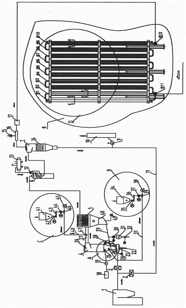
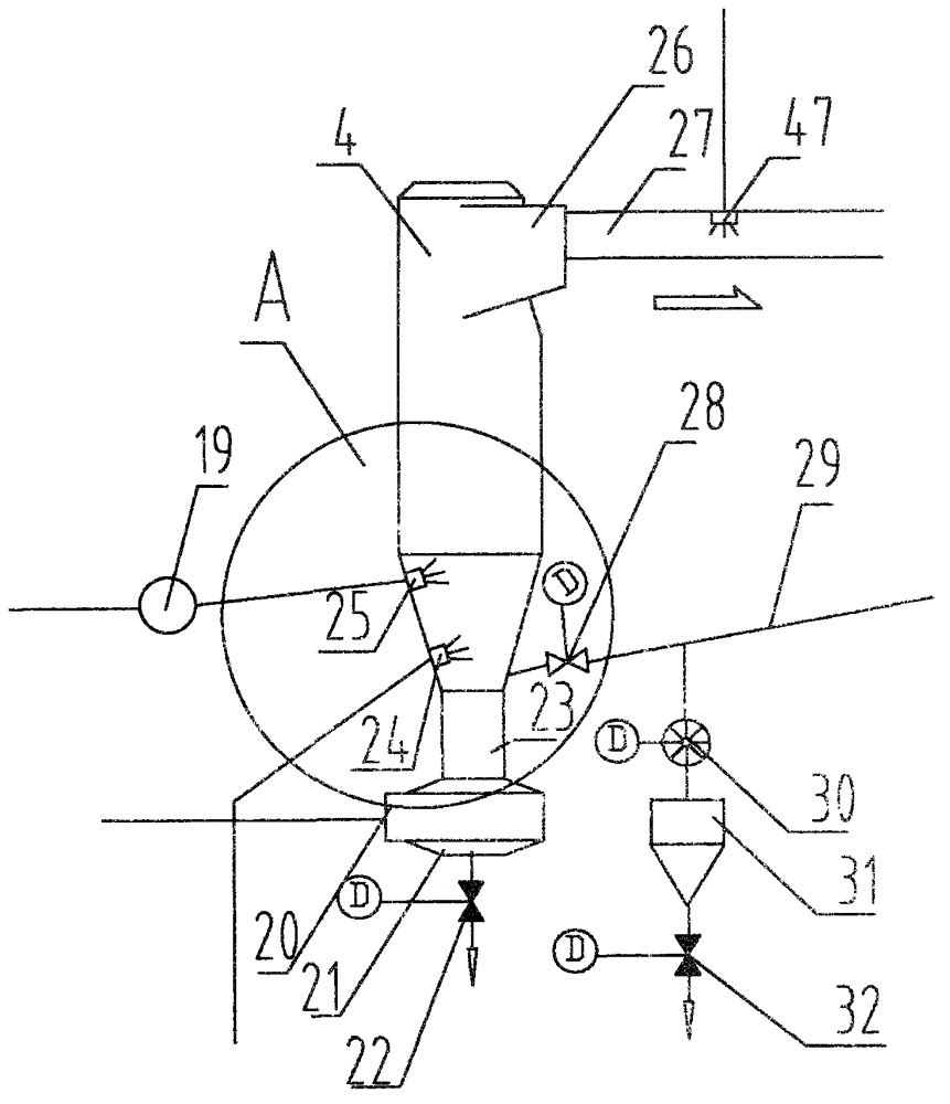
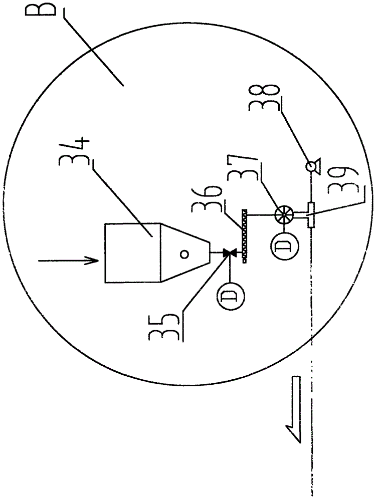
[0022] The present invention will be further described below in conjunction with the accompanying drawings.

[0023] Such as figure 1 , figure 2 , image 3 , Figure 4 , Figure 5 , Figure 6 , Figure 7 , Figure 8 , Figure 9 , Figure 10 , Figure 11 As shown, the present invention is an incinerator flue gas deacidification and denitrification device, comprising an incinerator 1, an electric air inlet valve 3, a reaction tower 4, a bag filter 5, a heat pipe heat exchanger 6, an SCR reactor 7, an ammonia gas The carburetor 8 is characterized in that: the incinerator 1 is sequentially connected with an electric air inlet valve 3, a reaction tower 4, a bag filter 5, a heat pipe heat exchanger 6, an SCR reactor 7, and an ammonia gasifier 8, and the incinerator A bypass pipeline 11 is connected between the furnace 1 and the inlet of the electric air inlet valve 3, the bypass pipeline 11 is connected to the inlet of the main fan 9, the outlet of the main fan 9 is conne...


PUM


Abstract

An incinerator flue gas deacidification and denitration device comprises an incinerator, an electric air inlet valve, a reaction tower, a bag-type dust remover, a heat pipe exchanger, an SCR reactor and an ammonia vaporizer and is characterized in that the incinerator is sequentially connected with the electric air inlet valve, the reaction tower, the bag-type dust remover, the heat pipe exchanger, the SCR reactor and the ammonia vaporizer, a bypass pipeline is connected between the incinerator and an inlet of the electric air inlet valve and connected with an inlet of a main fan, an outlet of the main fan is connected with a chimney, a bypass valve is arranged on the bypass pipeline, an outlet of the electric air inlet valve is connected with a gas inlet of the reaction tower, the lower portion of the gas inlet of the reaction tower is connected with a conical dust collecting groove, the conical dust collecting groove is connected with an electric cindervalve, and the upper portion of the gas inlet of the reaction tower is connected with a throat pipe. Acid gas and nitric oxide in flue gas generated in the household garbage incinerator can be removed, and harmful pollutant such as dioxin and heavy metal in the flue gas are adsorbed so that the flue gas can be exhausted in an up-to-standard mode and prevented from polluting the environment.

Description

technical field [0001] The invention relates to an incinerator flue gas deacidification and denitrification device, which is used for purifying flue gas produced by domestic garbage incinerators, and belongs to the technical field of environmental protection. Background technique [0002] In the existing technology, the flue gas between 850 ° C and 1100 ° C generated after the domestic waste is fully incinerated, the denitrification process mainly sprays ammonia solution, urea solution or other liquid nitrogen-containing reducing agents directly into the flue gas channel After atomization in the temperature range of 850℃~1100℃, it decomposes into ammonia gas. The ammonia gas reacts with the nitrogen oxides in the flue gas to form harmless substances such as nitrogen and water, and then enters the waste heat boiler. The 550℃ waste heat boiler flows out of the waste heat boiler The flue gas at ~600°C is cooled to 180°C by spray cooling equipment to remove acid gas, and then fi...

Claims


Application Information

Patent Timeline
Patent Type & Authority Applications(China)
IPC IPC(8): B01D53/75B01D53/60B01D53/68F23J15/00
CPCY02A50/20
Inventor 吴浩仑杨青吴志强
Owner WUXI HUAXING ELECTRIC POWER ENVIRONMENTAL PROTECTION REPAIRING & MFG
Why Eureka
Try Eureka