Turbulent tube grid tower capable of improving desulfurization efficiency

A desulfurization efficiency and turbulent tube technology, applied in the field of turbulent tube grid towers and wet flue gas desulfurization equipment, can solve the problems of increasing the liquid flux of non-blocking parts, shutting down for maintenance, and high operating costs, achieving high promotion and application value, maintenance Easy management and low operating cost

Inactive Publication Date: 2016-08-24
DATANG ENVIRONMENT IND GRP
View PDF8 Cites 12 Cited by
  • Summary
  • Abstract
  • Description
  • Claims
  • Application Information

AI Technical Summary

Problems solved by technology

The manufacturing process of the porous tray device that acts as a turbulence in the tray tower is very complicated. The raw material of the device is made of expensive high-strength alloy materials, and due to its porous characteristics, the tray is easily blocked. Once blocked, the entire absorption tower will be damaged. The flow field will become more non-uniform and increase the liquid flux in the non-clogged part, which will cause more serious blockage and even require shutdown for maintenance in some cases
In addition, the device resistance of the tray tower is also relatively large, and it needs to be equipped with a high-power blower or induced draft fan, so the strength of the pipeline is also high, which will greatly increase the operating cost.
[0005] Another type that is widely used is the rotary sink coupling tower. The rotary sink coupling tower also has the problems of complicated manufacturing process, difficult cleaning, high resistance, high production and operating costs, and the rotary sink coupling tower needs to achieve ideal The desulfurization effect requires a lot of calculations to adjust the inclination angle, size and layout of the swirl plate according to the working environment. Once the working environment changes, the desulfurization efficiency of the swirl coupling tower may decrease

Method used


Image

  • Turbulent tube grid tower capable of improving desulfurization efficiency
  • Turbulent tube grid tower capable of improving desulfurization efficiency
  • Turbulent tube grid tower capable of improving desulfurization efficiency

Examples


Embodiment 1

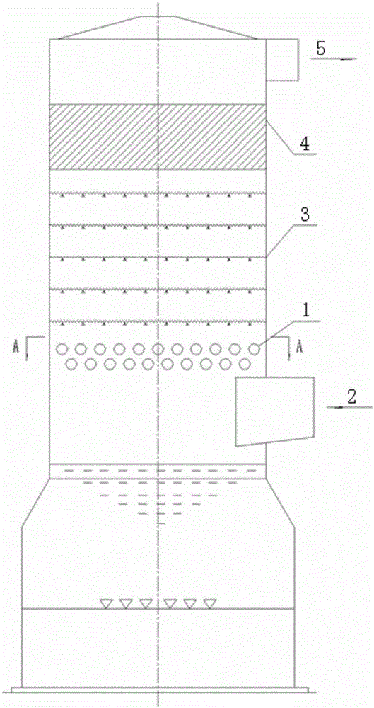
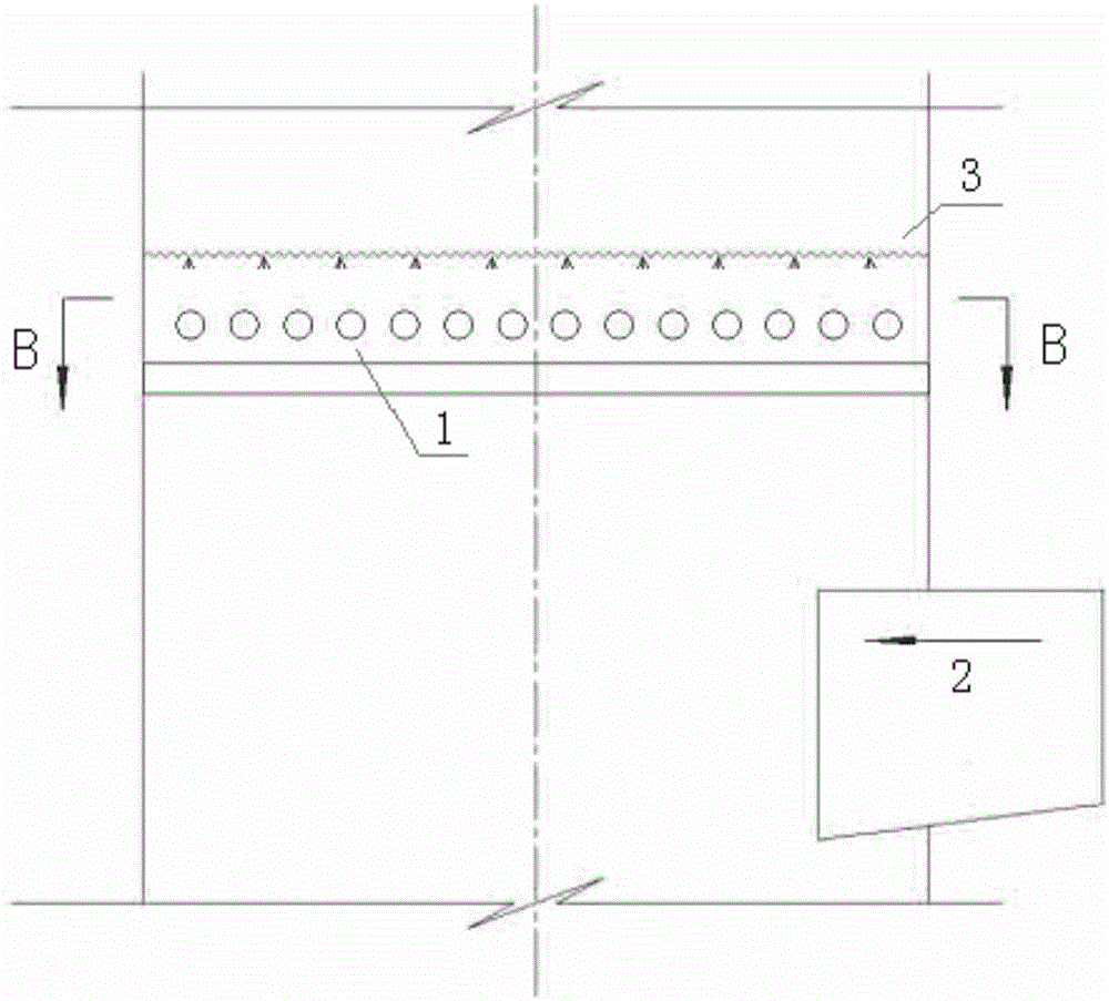
[0048] Such as figure 1As shown, the turbulent pipe grid tower for improving desulfurization efficiency of the present invention includes a flue gas inlet 2, a spray layer 3, a demister 4 and a flue gas outlet 5; between the flue gas inlet 2 and the spray layer 3, a Tube grid structure 1, including at least two layers of tube rows arranged in parallel layers; the tube row includes several parallel tubes; The projections of are non-coincident or partially co-incident. The pipe grid structure 1 is installed at 1.5-2.5 meters above the flue gas inlet 2 . The vertical distance between the flue gas inlet and the spray layer is 3-5 meters. However, the height of the swirl device in the swirl coupling tower is about 2 meters, so the distance between the flue gas inlet and the first layer of spraying is relatively large, at least 4 meters is required to ensure a sufficient installation position. Therefore, compared with the swirl-sink coupling tower, the tower height of the turbule...

Embodiment 2

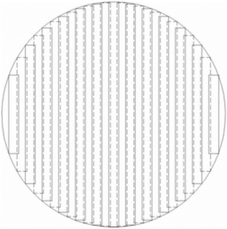
[0055] Such as image 3 and Figure 4 As shown, some adjustments are made on the basis of Embodiment 1, wherein the projections in the vertical direction of the tubes in one tube row and the tubes in the other tube row are perpendicular to each other. The simulated flow field calculation shows that the vertical arrangement of the tube spaces in adjacent tube columns can also obtain better desulfurization effect. The specific calculation process of the simulated flow field is as follows:

[0056] Fluent flow field simulation software is used to simulate the flue gas flow field under different porosity arrangements. It can be seen that the vertical arrangement between the tube rows can also obtain better turbulent flow effects, and the flue gas flow field is very uniform after passing through the device. , can better avoid the problem of sticking flow.

[0057] A) Layout parameters: the pipe diameter is 65mm, the horizontal spacing is fixed at 115mm, and the horizontal spacin...

Embodiment 3

[0059] Such as Figure 5 and Figure 6 As shown, the tubes in the tube row can also be elliptical tubes with a minor axis of the outer wall of 30-70mm and an ellipticity of 0.4-0.7, and the tubes in one tube row are staggered and parallel to the tubes in the other tube row. The specific calculation process of the simulated flow field is as follows:

[0060] Fluent flow field simulation software is used to simulate the flue gas flow field under different porosity arrangements. It can be seen that when using elliptical tubes, the width of the flow channel between the tubes can be increased, the range of turbulent flow between the tubes can be increased, and it can be appropriately reduced. The flow velocity between the pipes reduces the impact of the airflow on the pipe fittings.

[0061] A) Layout parameters: the size of the elliptical tube is 84*65mm, the horizontal spacing is 114mm, and the vertical spacing is 100mm; the velocity cloud diagram and velocity vector diagram ar...


PUM

PropertyMeasurementUnit
diameteraaaaaaaaaa
sizeaaaaaaaaaa
sizeaaaaaaaaaa

Abstract

The invention provides a turbulent pipe-grid tower for improving desulfurization efficiency. By increasing the pipe grid structure to uniformly distribute the flue gas flow field, uniformly spray the slurry, and form a liquid-holding layer on the upper part of the device, the gas-liquid contact area is increased, thereby improving the desulfurization efficiency. At the same time, the liquid-holding layer can also play a certain role in dust removal. And compared with the tray tower and the rotary sink coupling tower, its structure is simple, the manufacturing process is also simplified, the resistance is also greatly reduced, the production and operation costs are reduced, and it is also convenient for maintenance. The technical solution adopted is: a turbulent pipe grid tower for improving desulfurization efficiency, including tower body, flue gas inlet and spray layer; a pipe grid structure is arranged between the flue gas inlet and spray layer, including parallel layered arrangement There are at least two layers of tube arrays; the tube array includes several parallel tubes; the vertical projections of any one tube and the tubes in the adjacent tube arrays of the tube array do not overlap or partially overlap.

Description

technical field [0001] The invention relates to the technical field of environmental protection, in particular to wet flue gas desulfurization equipment, and in particular to a turbulent flow pipe-grid tower for improving desulfurization efficiency. Background technique [0002] The "Coal Power Energy Conservation and Emission Reduction Upgrading and Transformation Action Plan (2014-2020)" requires the eastern region (Liaoning, Beijing, Tianjin, Hebei, Shandong, Shanghai, Jiangsu, Zhejiang, Fujian, Guangdong, Hainan and other 11 provinces and cities) to build new coal-fired power plants. The emission concentration of air pollutants from generating units has basically reached the emission limit of gas turbine units (that is, under the condition of a reference oxygen content of 6%, the emission concentrations of soot, sulfur dioxide, and nitrogen oxides are not higher than 10, 35, and 50 mg / m3 respectively). In principle, newly-built units in the region (8 provinces including ...

Claims


Application Information

Patent Timeline
Patent Type & Authority Applications(China)
IPC IPC(8): B01D53/80B01D53/50B01D47/00B01D50/00
Inventor 赵怡凡谷小兵肖志均申镇王长清江澄宇齐勇
Owner DATANG ENVIRONMENT IND GRP
Why Eureka
Try Eureka