

Shielding optical window and preparation method thereof
A light shielding and spin-coating technology, which is applied in the directions of magnetic/electric field shielding, ion implantation plating, coating, etc., can solve the problems of easy deliquescence, doping, and limited applicability of wet coating, and achieve firmness and The effect of excellent wear resistance
- Summary
- Abstract
- Description
- Claims
- Application Information
AI Technical Summary
Problems solved by technology
Method used
Image

Examples
preparation example Construction
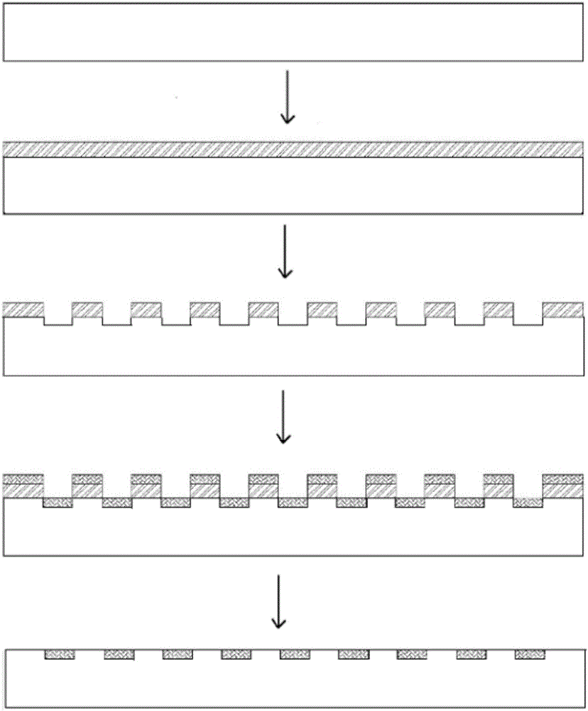
[0026] The invention provides a kind of preparation method of shielding light window, comprises the following steps (such as figure 1 shown):
[0027] (1) cleaning the substrate;
[0028] (2) coating protective layer;
[0029] (3) etching the protective layer and the substrate;
[0030] (4) Carry out sputter coating on the substrate surface after etching;
[0031] (5) Remove the protective layer to obtain the shielded light window.
[0032] The above schemes can already complete the preparation of the shielding light window, and on this basis, the preferred scheme is given:
[0033] Preferably, the protective layer has a thickness of 5-15 μm and is made of polyvinyl alcohol or photoresist.
[0034] Preferably, the step (2) is coated by centrifugal spin coating or spray coating.
[0035] Preferably, the etching adopts a square or circular line structure, the line width is 5-12 μm, the period is 250-800 μm, and the etching depth is 3-15 μm.
[0036] Preferably, the sputte...
Embodiment 1
[0042] Fabricate 8-10.5μm transparent, 1-10GHZ shielded metal grid on CVD ZnS substrate
[0043] (1) Use ultrasonic waves to clean and dry the ZnS substrate: use an ultrasonic cleaning unit with a frequency of 50KHz to clean the ZnS substrate, and the ultrasonic action time is 15 minutes, and then bake the substrate in an oven at 120°C for 10 minutes to dry.
[0044] (2) Utilize centrifugal spin-coating method, the AZ4620 photoresist protective layer that thickness is 5 μm is coated on ZnS substrate surface: Utilize spraying method, be the AZ4620 photoresist protective layer that 5 μm thickness is coated on ZnS substrate surface, its The parameters are: PEEK tube diameter 175 μm, air pressure 0.2 MPa, spraying distance 40 mm, nozzle X-axis moving speed 50 mm / s, Y-axis moving step 2 mm, spraying times 1 time.
[0045] (3) Using a wavelength of 1064nm and a pulse width of 10 -15 S laser, etch the AZ4620 photoresist protective layer and the substrate, the metal grid structure i...
Embodiment 2
[0050] Fabricate 3-5μm transmission and 1-18GHZ shielding metal grid on calcium aluminum barium infrared glass substrate
[0051] (1) Ultrasonic wave is used to clean and dry the calcium aluminum barium infrared glass substrate; the calcium aluminum barium infrared glass substrate is cleaned by an ultrasonic cleaning unit with a frequency of 50KHz. Bake in an oven for 12 minutes to dry the substrate.
[0052] (2) Using the spraying method, apply polyvinyl alcohol with a thickness of 15 μm on the surface of the calcium aluminum barium infrared glass substrate as a protective layer; polyvinyl alcohol is used as a protective layer, which is low in cost and greatly reduces the processing cost of the shielding light window , using the spraying method to coat a polyvinyl alcohol protective layer with a thickness of 15 μm on the surface of the calcium aluminum barium substrate. The parameters are: PEEK tube diameter 175 μm, air pressure 0.3MPa, spraying distance 60mm, nozzle X-axis m...
PUM
| Property | Measurement | Unit |
|---|---|---|
| Thickness | aaaaa | aaaaa |
| Thickness | aaaaa | aaaaa |
| Thickness | aaaaa | aaaaa |
Abstract
Description
Claims
Application Information