Nanowire cold cathode electron source array with self-aligned focusing structure and manufacturing method thereof

A production method and nanowire technology, applied in cold cathode manufacturing, electrode system manufacturing, discharge tube/lamp manufacturing, etc., can solve problems such as difficult control of beam current, imaging distortion, intake, etc., and solve complex electrode lead layout problem, improve the effect of divergence problem

Active Publication Date: 2016-11-23
SUN YAT SEN UNIV
View PDF13 Cites 12 Cited by
  • Summary
  • Abstract
  • Description
  • Claims
  • Application Information

AI Technical Summary

Problems solved by technology

At present, most commercial X-ray tubes are hot-cathode X-ray tubes. Although the hot-cathode X-ray tube is very mature, there are still some disadvantages: (1) The filament in the hot-cathode X-ray tube needs to be heated, and the power consumption is large. , the working temperature is high, and it needs to be equipped with an additional cooling device, which is not conducive to reducing its energy consumption and reducing its volume
(2) Due to working under high temperature conditions, the filament is often more likely to react with the remaining gas in the tube and volatilize, shortening its life
(3) The electrons emitted by the filament are randomly distributed, and the electron energy distribution range is wide, making it difficult for the electrons to be focused, which limits the improvement of its spatial resolution
(4) The response speed is slow, and the beam current is not easy to control, which limits the improvement of its time resolution
Therefore, the X-ray tube needs to be placed far away from the target object to perform global imaging on it, which occupies a large area, and the radial X-ray beam is easy to cause imaging distortion.
In addition, in medical diagnostic applications, subjects may ingest unnecessary X-ray radiation, and operators may also be exposed to X-ray radiation environment

Method used


Image

  • Nanowire cold cathode electron source array with self-aligned focusing structure and manufacturing method thereof
  • Nanowire cold cathode electron source array with self-aligned focusing structure and manufacturing method thereof
  • Nanowire cold cathode electron source array with self-aligned focusing structure and manufacturing method thereof

Examples


Embodiment 1

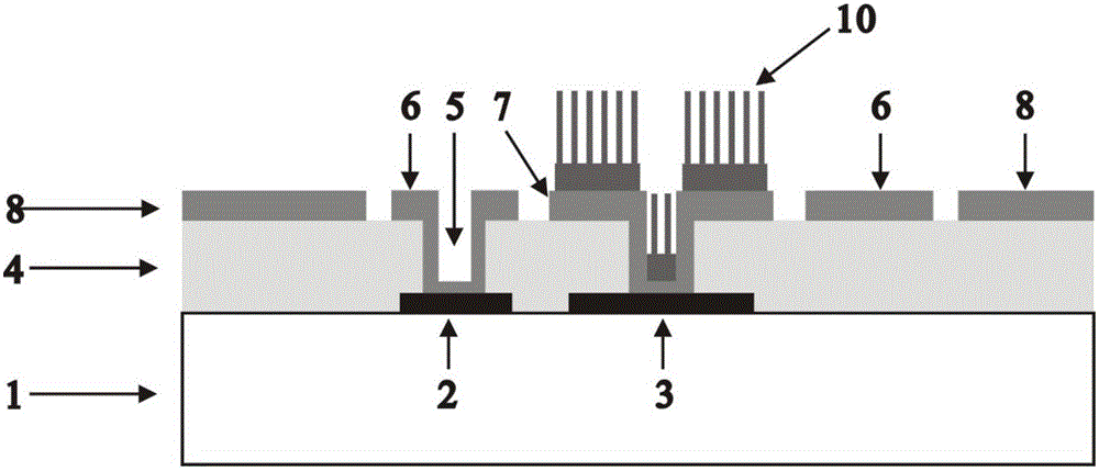
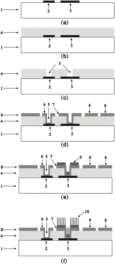
[0057] This example presents the manufacturing process of a nanowire cold cathode electron source array with a self-aligning focusing structure that uses zinc oxide nanowires as the cold cathode material and can be addressed row by row. For specific manufacturing process steps, please refer to the attached figure 2 .

[0058] First, the glass substrate was ultrasonically cleaned with acetone, ethanol, and deionized water for 20 minutes, and then blown dry with nitrogen. On the glass substrate, the bottom cathode electrode strips and the bottom grid electrode strips parallel to each other are prepared by photolithography, DC magnetron sputtering vacuum coating technology and lift-off process. The material of the two bottom electrode strips is chromium, and its thickness is about 120nm. Next, a layer of insulating film is deposited on the above two bottom electrode strips by means of plasma enhanced chemical vapor deposition. The insulating film is a silicon dioxide film with ...


PUM


Abstract

The invention discloses a nanowire cold cathode electron source array with a self-aligned focusing structure and a manufacturing method thereof. The electron source array structure comprises a substrate, a bottom cathode electrode strip, a bottom gate electrode strip, an insulating layer configured to cover the above electrode strips, an annular top gate electrode, a top cathode electrode, a focusing electrode, and a circular nanowire cold cathode array. The bottom cathode electrode strip and the bottom gate electrode strip are arranged on the substrate and are positioned in parallel with each other. The annular top gate electrode, the top cathode electrode and the focusing electrode are manufactured above the insulating layer and are connected with the bottom corresponding electrode strips through etching through holes in the insulating layer. The circular nanowire cold cathode array is manufactured on the top cathode electrode. The invention further discloses a manufacturing method of the nanowire cold cathode electron source array. According to the technical scheme of the invention, the nanowire cold cathode electron source array is provided with the self-aligned focusing structure, so that the row-by-row addressing function can be realized. The manufacturing method is simple, and the prepared nanowire cold cathode electron source array is good in capability of regulating and controlling electron emission and focusing electron beams. Therefore, the nanowire cold cathode electron source array and the manufacturing method thereof have an important application prospect in the aspect of flat plate X-ray sources.

Description

technical field [0001] The invention belongs to the technical field of vacuum microelectronics, in particular to a structure and a manufacturing method of a nanowire cold cathode electron source array with a focusing structure and a row-by-row addressing. Background technique [0002] X-ray plays an important role in medical diagnosis and treatment, biological research, industrial flaw detection, security inspection and scientific research, especially in medical diagnosis, X-ray diagnosis has become one of the diagnostic techniques commonly used in hospitals. At present, most commercial X-ray tubes are hot-cathode X-ray tubes. Although the hot-cathode X-ray tube is very mature, there are still some disadvantages: (1) The filament in the hot-cathode X-ray tube needs to be heated, and the power consumption is large. , the working temperature is high, and an additional cooling device is required, which is not conducive to reducing its energy consumption and reducing its volume....

Claims


Application Information

Patent Timeline
Patent Type & Authority Applications(China)
IPC IPC(8): H01J1/304H01J9/02
CPCH01J1/304H01J9/025
Inventor 陈军赵龙刘垣明陈道坤邓少芝许宁生佘峻聪
Owner SUN YAT SEN UNIV
Why Eureka
Try Eureka