Air-breathing photo-assisted biomass fuel cell and use thereof

A fuel cell, self-breathing technology, applied in the direction of aqueous electrolyte fuel cells, fuel cells, battery electrodes, etc., can solve the problems of few types, limit the absorption and utilization of sunlight, and achieve the effect of clean conversion process

Inactive Publication Date: 2016-12-28
DALIAN INST OF CHEM PHYSICS CHINESE ACAD OF SCI
View PDF3 Cites 18 Cited by
  • Summary
  • Abstract
  • Description
  • Claims
  • Application Information

AI Technical Summary

Problems solved by technology

[0007] It can be seen that the semiconductor materials currently used in photo-assisted biomass fuel cells are mainly TiO 2 Lord, WO 3 There are also some studies, the species is still less, and due to TiO 2 and WO 3 The gap is wide, which limits the absorption and utilization of sunlight

Method used


Image

  • Air-breathing photo-assisted biomass fuel cell and use thereof
  • Air-breathing photo-assisted biomass fuel cell and use thereof
  • Air-breathing photo-assisted biomass fuel cell and use thereof

Examples


Embodiment 1

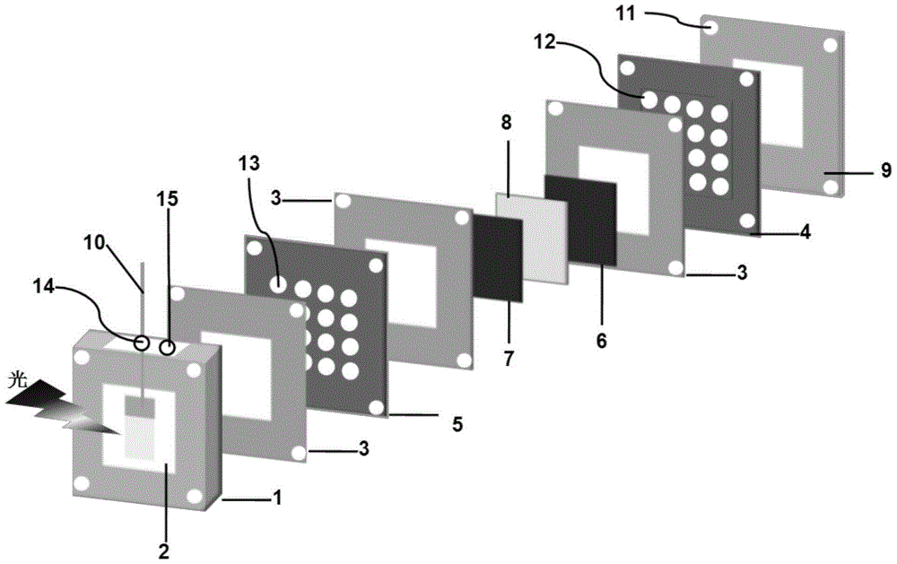
[0060] Such as figure 1 Shown is a self-breathing photo-assisted biomass fuel cell, including liquid storage cavity 1, optical window 2, sealing gasket 3, cathode collector plate 4, anode fixing plate 5, cathode gas diffusion layer 6, anode diffusion layer 7, Membrane electrode 8, end plate 9, photoanode 10.

[0061] Specifically, a sealing gasket 3 is respectively provided on the inner side of the anode fixing plate 5 and the cathode current collecting plate 4, a membrane electrode 8 is provided between the two sealing gaskets 3, and the membrane electrode 8 is provided with a cathode on the side of the cathode current collecting plate 4. The gas diffusion layer 6, the membrane electrode 8 is provided with an anode diffusion layer 7 on the side of the anode fixing plate 5, the cathode current collector plate 4 is provided with an end plate 9; the anode fixing plate 5 is provided with a liquid storage chamber 1, a liquid storage chamber There is a sealing gasket 3 between 1 and t...

Embodiment 2

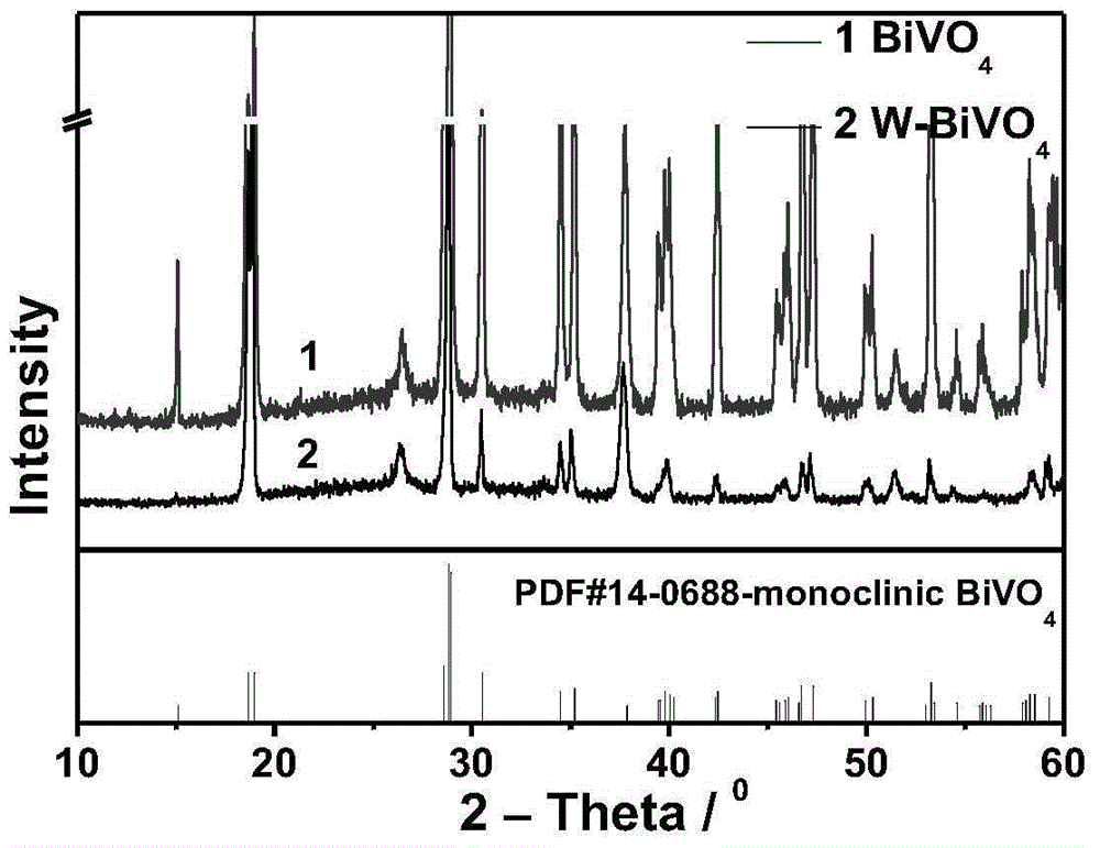
[0064] BiVO 4 And W-BiVO 4 Preparation of photoanode:

[0065] BiVO 4 Electrode or W-BiVO 4 The synthesis steps of the electrode are as follows:

[0066] BiVO 4 Preparation of photoanode: synthesis by constant potential deposition method. 202mL water plus 11mL 65% by mass concentrated HNO 3 , Said 8.75mmol VOSO 4 .xH 2 O is dissolved in the above solution, and 1.2133g Bi(NO 3 ) 3 .5H 2 O, 52g anhydrous sodium acetate adjust the pH to about 5.1, then add nitric acid to adjust the pH to 4.7. Use the above solution as the electrolyte, Pt sheet as the counter electrode, FTO as the working electrode, saturated calomel electrode SCE as the reference electrode, under the condition of 70℃ water bath constant temperature, use CHI760D electrochemical workstation to control the potential 1.855V vs. SCE, and deposit for 40 minutes Take out the cleaning, roast it in the air at 500℃ for 1h, the heating rate is 2℃ / min, and finally soak it with 1mol / L KOH for 15min to remove V 2 O 5 Impurities, t...

Embodiment 3

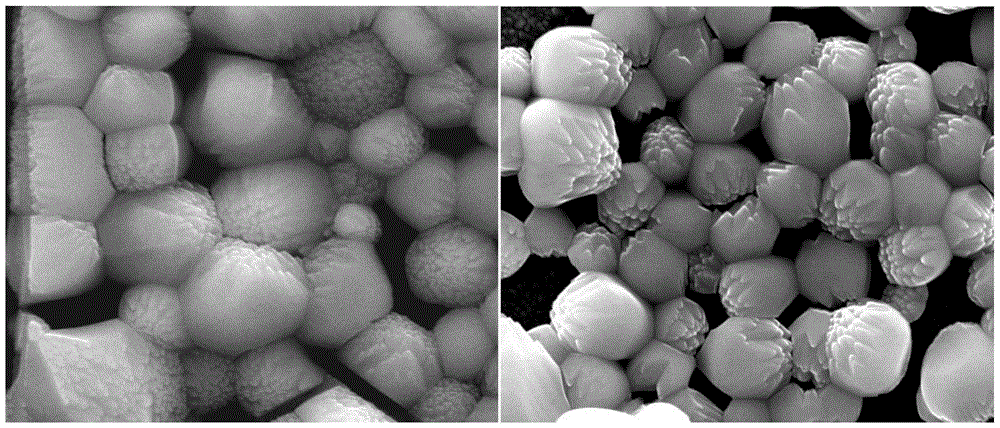
[0070] BiVO 4 And W-BiVO 4 Morphology characterization of photoanode:

[0071] BiVO 4 The electrode is composed of approximately spherical particles connected with each other, W-BiVO doped with W 4 Keep BiVO 4 The topography of the electrode, see the result image 3 .


PUM


Abstract

The invention relates to an air-breathing photo-assisted biomass fuel cell. The fuel cell can transform optical energy and biomass energy into electric energy through optical excitation. The fuel cell comprises a light window, a liquid storage chamber, sealing washers, an anode fixed plate, an anode diffusion layer, a membrane electrode, a cathode gas diffusion layer, a cathode collector plate and an end plate. The inner sides of the anode fixed plate and the cathode collector plate are respectively provided with the sealing washers. The membrane electrode is arranged between the two sealing washers. The membrane electrode located at one side of the cathode collector plate is provided with the cathode gas diffusion layer. The membrane electrode located at one side of the anode fixed plate is provided with the anode diffusion layer. The outer side of the cathode collector plate is provided with the end plate. The outer side of the anode fixed plate is provided with the liquid storage chamber. The sealing washer is arranged between the liquid storage chamber and the anode fixed plate. The light window is laid in the hollow part of the middle of the front side of the liquid storage chamber. The light window is used as a light entrance port. A photo anode and a fuel solution are arranged in the liquid storage chamber. The fuel cell provides a cheap and eco-friendly novel approach of conversion of solar energy and biomass energy into electric energy.

Description

Technical field [0001] The invention belongs to the field of fuel cells, and specifically relates to a self-breathing photo-assisted biomass fuel cell and its application. In the self-breathing photo-assisted biomass fuel cell, light energy and biomass energy are converted into electrical energy and released. Background technique [0002] Energy and environmental issues are two major issues facing the survival and sustainable development of human society. At present, the main energy systems in the world are mainly based on C-containing fossil fuels such as petroleum and coal. Energy conversion is mainly realized through the heat engine process. Due to the limitation of the Carnot cycle, not only the conversion efficiency is low, but also serious energy waste. And produce a lot of dust, CO 2 The pollution of the atmosphere, water and soil caused by harmful substances such as nitrogen oxides, sulfur oxides, and noise, seriously threatens the living environment of mankind, and the d...

Claims


Application Information

Patent Timeline
Patent Type & Authority Applications(China)
IPC IPC(8): H01M8/22H01M8/08H01M4/90
CPCH01M4/9016H01M8/08H01M8/22Y02E60/50
Inventor 李灿张丙青施晶莹
Owner DALIAN INST OF CHEM PHYSICS CHINESE ACAD OF SCI
Why Eureka
Try Eureka