

Photovoltaic power generation system and manufacture method
A solar photovoltaic and power generation system technology, applied in the field of solar power generation, can solve problems such as damage to the power generation efficiency of solar cells, and achieve the effect of convenient manufacturing process and easy realization.
- Summary
- Abstract
- Description
- Claims
- Application Information
AI Technical Summary
Problems solved by technology
Method used
Image

Examples
Embodiment 1
[0070] The fluorescent material is organic perovskite material MAPbBr 3 , whose spectral properties are as Figure 4a , Figure 4b , Figure 4c , Figure 4d shown.
[0071] Figure 4a for MAPbBr 3 Material MABr / PbBr 2 Steady-state PL spectrum with molar ratio reduced from 2:1 to 1:1;
[0072] Figure 4b for MAPbBr 3-x Cl x Material MABr / PbBr 2 / PbCl 2 Steady-state PL spectrum with molar ratio changed from 2:0.8:0.2 to 2:0.2:0.8;
[0073] Figure 4c for MAPbBr 3-x Cl x Material MABr / PbBr 2 / PbCl 2 Steady-state PL spectrum with molar ratio changed from 1.5:0.8:0.2 to 1.5:0.2:0.8;
[0074] Figure 4d for MAPbBr 3-x Cl x Material MABr / PbBr 2 / PbCl 2 Steady-state PL spectra for varying molar ratios from 1:0.8:0.2 to 1:0.2:0.8.
[0075] Preparation of MAPbBr by solution method, sol-gel method and solid-state sintering method 3 Organic fluorescent substances can adjust the position of the luminescence peak by changing the inorganic ratio, so that the fluoresc...
Embodiment 2
[0080] The fluorescent material is organic perovskite material MAPbBr 3 Composite with organic dye Lumogen F Yellow 170. The organic composite fluorescent substance is prepared by a solution method, a sol-gel method, or a solid phase sintering method. By changing the inorganic ratio and modulating the position of the luminescence peak, the fluorescence emission peak can be matched with the absorption spectrum of the solar cell. By changing the ratio of organic dyes and organic perovskite materials, the fluorescence quantum efficiency of fluorescent substances can be changed. The synthesized perovskite fluorescent material has the characteristics of broadband ultraviolet-visible light absorption and high quantum yield, and can convert blue-violet light into yellow-green light for emission.
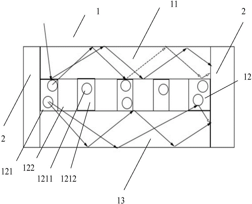
[0081] Use ultra-white glass to make the substrate 11, choose ultra-white glass with a light transmittance>91%, and a refractive index>1.5, use optical glass to make the substrate 13, cho...
Embodiment 3
[0086] Lumogen F Yellow170, Lumogen FOrgange 240 and MAPbBr 3 / CsPbBr 3Combined to prepare colloid and powder materials. By changing the inorganic ratio and modulating the position of the luminescence peak, the fluorescence emission peak can be matched with the absorption spectrum of the solar cell. By changing the ratio of organic dyes and organic perovskite materials, the fluorescence quantum efficiency of fluorescent substances can be changed. The synthesized perovskite fluorescent material has the characteristics of broadband ultraviolet-visible light absorption and high quantum yield, and can convert blue-violet light into yellow-green light for emission.
[0087] The substrate 11 and the substrate 13 are made of optical glass, the optical glass with a refractive index as high as 1.83 is selected, and high light transmittance is ensured, and fluorescent substances are deposited on the optical glass.
[0088] Dissolve 0.075g of the organic composite fluorescent substanc...
PUM
 Abstract
Description
Claims
Application Information