

Hydrogen energy vehicle power system for ambient air purification
A power system and ambient air technology, applied in the direction of fuel system, charging system, air quality improvement, etc., can solve the problem of difficult market operation of hydrogen fuel vehicles
- Summary
- Abstract
- Description
- Claims
- Application Information
AI Technical Summary
Problems solved by technology
Method used
Image

Examples
Embodiment 1
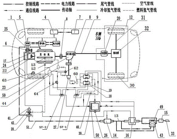
[0035] The present invention purifies the hydrogen energy vehicle power system of ambient air, such as figure 1 As shown, it includes vehicle body 1, control system, transmission system 12, catalytic converter 14, exhaust gas treatment and emission system, inverter 5, No. 1 motor-generator 6, No. 2 motor-generator 29, hydrogen fuel engine 25, Metal hydride storage tank 10, hydrogen surge tank 59, battery 3, hydrogen compression unit 18, expander 27, turbocharger 28, No. 1 lithium bromide refrigerator 57-1, No. 2 lithium bromide refrigerator 57-2, air filter 42 and power combiner 23 . The control system includes a central controller 4, a power bus 2, and a manual-automatic driving system 7. The central controller 4 communicates with the power bus, battery and inverter 5, and is connected to the manual-automatic driving system. The battery is connected to the power bus and to the inverter circuit, and the inverter is connected to the No. 1 motor-generator and No. 2 motor-genera...
Embodiment 2
[0045] Another embodiment of the present invention is as figure 2 As shown, it includes vehicle body 1, control system, transmission system 12, catalytic converter 14, exhaust gas treatment and emission system, inverter 5, No. 1 motor-generator 6, hydrogen fuel engine 25, metal hydride storage tank 10, hydrogen gas Regulator tank 59, battery 3, hydrogen compression unit 18, expander 27, turbocharger 28, No. 1 lithium bromide refrigerator 57-1, No. 2 lithium bromide refrigerator 57-2, air filter 42 and power combiner twenty three. The battery is connected to the power bus and to the inverter circuit, and the inverter is connected to the No. 1 motor-generator circuit. The No. 1 motor-generator is connected to one end of the crankshaft 22 of the hydrogen fuel engine through the pulley 17, and the other end of the crankshaft of the hydrogen fuel engine is connected to the power combiner 23 through the clutch 8. The expander is connected to the power combiner through the clutch, ...
Embodiment 3
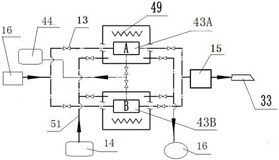
[0048] Yet another embodiment of the present invention is as image 3 As shown, the power system is used as a fixed device, including a hydrogen fuel engine 25, a No. 1 generator 66, a hydrogen surge tank 59, a No. 2 generator 67, a hydrogen compressor unit 18, a residual hydrogen absorption unit 43, and a metal hydride storage tank 10. Tail gas treatment and emission system, substation 55, distribution station 56, expander 27, turbocharger 28, No. 1 lithium bromide refrigerator 57-1 and No. 2 lithium bromide refrigerator 57-2. The metal hydride storage tank is connected to the inlet of the expander through the No. 1 lithium bromide refrigerator, the hydrogen compression unit and the intermediate tank 60, and the outlet of the expander is connected to the hydrogen inlet 53 of the hydrogen fuel engine through the cold recovery device 62 and the hydrogen surge tank. The air inlet 41 is connected to the intake manifold through an air filter 42 and the boost section of the turboch...
PUM
 Abstract
Description
Claims
Application Information