Diesel engine part surface multilayer wear-resisting anti-friction thin film and preparing method thereof

A technology for diesel engines and parts, applied in the field of multi-layer films, can solve the problems of low life expectancy, low friction, and difficulty in meeting high load capacity, and achieve the effects of increasing service life, improving service life and improving surface performance.

Active Publication Date: 2017-06-20
LANZHOU INST OF PHYSICS CHINESE ACADEMY OF SPACE TECH
View PDF11 Cites 2 Cited by
  • Summary
  • Abstract
  • Description
  • Claims
  • Application Information

AI Technical Summary

Problems solved by technology

One of the key problems is the lubrication problem, the traditional electroplating method is difficult to achieve environmental friendliness
Liquid lubrication is difficult to meet the requirements of high load, low friction and long life
[0003] Most of the existing diesel engine parts use electroplating technology and liquid lubrication technology. The newer technology is diamond-like technology, but there are problems of not improving the service life and the efficiency is still low.

Method used


Image

  • Diesel engine part surface multilayer wear-resisting anti-friction thin film and preparing method thereof

Examples


Embodiment 1

[0027] Example 1 Taking the multi-layer wear-resistant and friction-reducing film on the surface of a diesel engine plunger as an example

[0028] (1) Chemical cleaning. Use petroleum ether, acetone, and alcohol to ultrasonically clean the base material of the diesel engine plunger, and the ultrasonic time for each solvent is 5 minutes.

[0029] (2) Heating and vacuuming. Ensure that the film is deposited within a certain temperature and vacuum range, the heating temperature is 160 °C, and the vacuum range is 2×10 -3 Pa.

[0030] (3) Plasma source (glow discharge) bombardment cleaning. Introduce argon gas into the vacuum chamber, turn on the plasma source to bombard and clean the substrate surface, and remove the attachments on the substrate surface. The flow rate of argon gas is 150 sccm, the plasma source current is 60A, the substrate bias voltage is 500V, and the bombardment time is 30min. .

[0031] (4) Deposit a Cr layer. Introduce argon gas, turn on the magnetron s...

Embodiment 2

[0037] Example 2 Taking the multi-layer wear-resistant and friction-reducing film on the surface of the tappet washer of a diesel engine as an example

[0038] (1) Chemical cleaning. Use petroleum ether, acetone, and alcohol to ultrasonically clean the base material of the diesel engine tappet gasket, and the ultrasonic time for each solvent is 5 minutes.

[0039] (2) Heating and vacuuming. Ensure that the film is deposited within a certain temperature and vacuum range, the heating temperature is 160 °C, and the vacuum range is 2×10 -3 Pa.

[0040] (3) Plasma source bombardment cleaning. Introduce argon gas into the vacuum chamber, turn on the plasma source to bombard and clean the substrate surface, and remove the attachments on the substrate surface. The flow rate of argon gas is 150 sccm, the plasma source current is 60A, the substrate bias voltage is 500V, and the bombardment time is 30min. .

[0041] (4) Deposit a Cr layer. Introduce argon gas, turn on the magnetron s...


PUM

PropertyMeasurementUnit
adhesivityaaaaaaaaaa
friction coefficientaaaaaaaaaa

Abstract

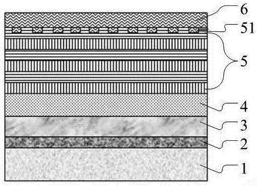
The invention relates to a diesel engine part surface multilayer wear-resisting anti-friction thin film. The surface of a diesel engine part sequentially comprises a Cr layer, a Cr / MeC transition layer, an MeC-DLC layer, an a-C:H soft and hard alternative layer and an MoS2 layer from inside to outside, wherein Me is a transition metal element. Firstly, the Cr layer is deposited on the surface of the diesel engine part through magnetron sputtering; secondly, the Cr / MeC transition layer is deposited through magnetron sputtering; thirdly, the MeC-DLC layer is deposited through a magnetron sputtering / plasma assisting chemical vapor phase composite deposition method; fourthly, the a-C:H soft and hard alternative layer is deposited through a plasma assisting chemical vapor phase composite deposition method; fifthly, a microtexture is etched on the a-C:H soft and hard alternative layer through a laser etching method; and finally the MoS2 layer is deposited through magnetron sputtering. By means of the thin film, the surface performance of the diesel engine part can be obviously improved, the service life of the diesel engine part surface multilayer wear-resisting anti-friction thin film is prolonged, and the energy using rate and reliability of the diesel engine part surface multilayer wear-resisting anti-friction thin film are improved.

Description

technical field [0001] The invention belongs to the field of surface treatment and vacuum treatment of diesel engine parts, and in particular relates to a diesel engine part surface prepared by using magnetron sputtering, plasma assistance and laser etching technology, which has good synergistic lubricating effect with diesel oil, high binding force and low friction coefficient. Low, low wear rate, long life multilayer film. Background technique [0002] With the increasing emphasis on environmental protection in our country, energy conservation and emission reduction has become an imperative and important topic. For diesel engines, reducing energy consumption and pollutant emissions is of great significance. One of the key issues is lubrication, and traditional electroplating methods are difficult to achieve environmental friendliness. Liquid lubrication is difficult to meet the requirements of high load, low friction, long life and so on. [0003] Most of the existing d...

Claims


Application Information

Patent Timeline
Patent Type & Authority Applications(China)
IPC IPC(8): C23C28/00C23C14/35C23C14/16C23C14/06C23C16/32C23C16/56
CPCC23C14/0635C23C14/165C23C14/352C23C16/32C23C16/56C23C28/32C23C28/343C23C28/44
Inventor 周晖杨拉毛草郑军张延帅张凯锋贵宾华郝宏苟世宁霍丽霞
Owner LANZHOU INST OF PHYSICS CHINESE ACADEMY OF SPACE TECH
Why Eureka
Try Eureka