Coaxial interference surface plasma microscopical method and coaxial interference surface plasma microscopical system based on pupil modulation
What is Al technical title?
Al technical title is built by PatSnap Al team. It summarizes the technical point description of the patent document.
A technology of surface plasmon and interference surface, applied in the field of plasma microscope system, to achieve the effect of less optical devices, low cost and simple system structure
Inactive Publication Date: 2017-06-20
BEIHANG UNIV
View PDF4 Cites 5 Cited by
Summary
Abstract
Description
Claims
Application Information
AI Technical Summary
This helps you quickly interpret patents by identifying the three key elements:
Problems solved by technology
Method used
Benefits of technology
Problems solved by technology
The disadvantage of this technology is that its lateral resolution is limited by the propagation length of the SPR wave, usually more than ten microns, which is much larger than the diffraction limit of conventional optical systems, that is, on the order of half a wavelength. A typical system is a prism-type SPR microscope system
Method used
Image
Click on the blue label to locate the original text in one second.
Reading with bidirectional positioning of images and text.
Examples
specific Embodiment approach 1
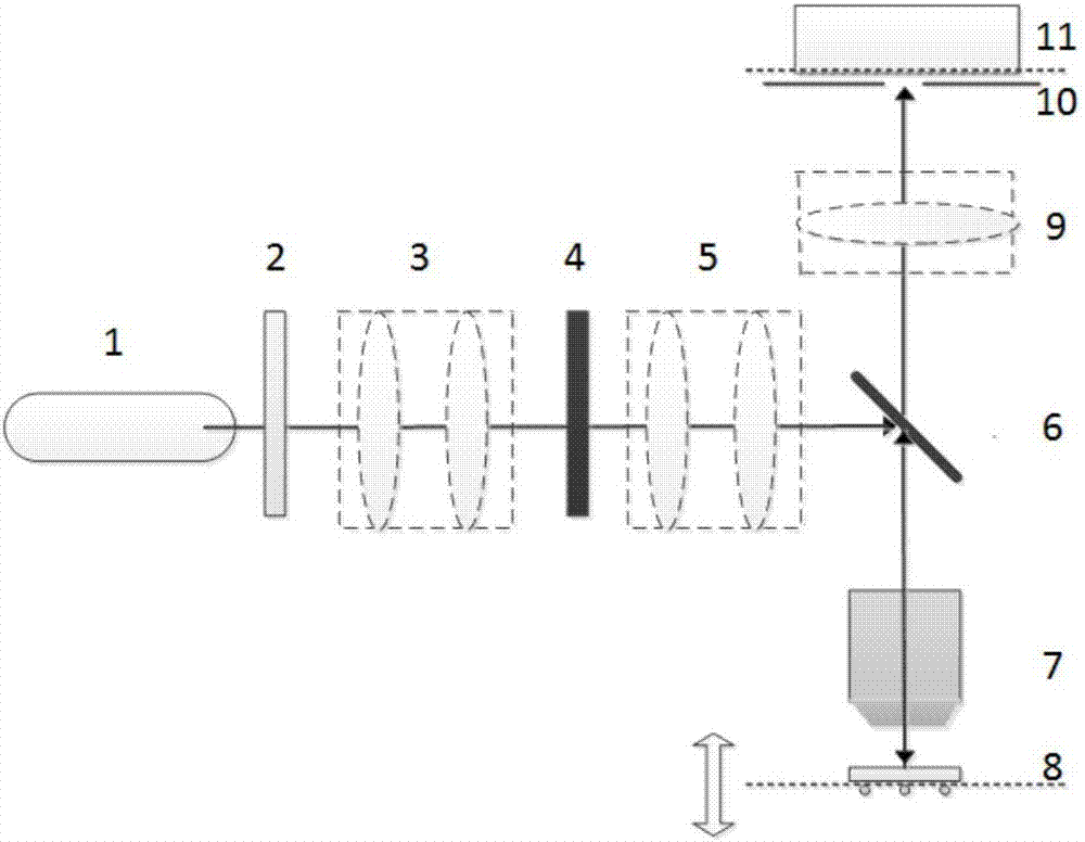
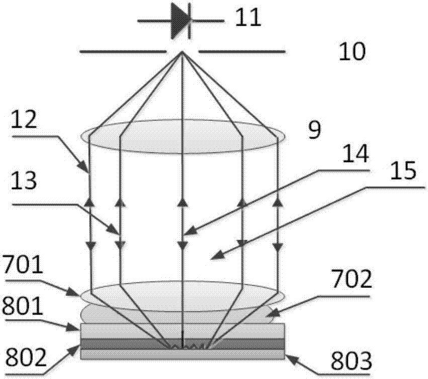
[0038] Specific embodiment one: the coaxial interference surface plasmon microscope system of a kind of rear focal plane pupil modulation described in the present embodiment, it comprises: Laser emitter (1), polarization modulation device (2), beam expander (3), spatial light modulator (4), projection lens (5), dichroic prism (6), oil immersion microscope objective lens (7), surface plasmon sample to be measured (8), imaging lens group (9), Confocal aperture (10), image sensor (11).
[0039] Laser emitter (1), polarization modulation device (2), beam expander (3), spatial light modulator (4), projection lens (5), beam splitter prism (6) are centered on the same optical axis; A microscope objective lens (7), a surface plasmon sample to be measured (8), an imaging lens group (9), a confocal aperture (10), and an image sensor (11). on the same optical axis.
[0040] The polarization modulation device (2) generally consists of a half glass and a polarizer, and the photosensitive...
specific Embodiment approach 2
[0053] Embodiment 2: The system layout of this embodiment is as described in Embodiment 1, but this embodiment provides a method for quickly scanning the surface microtopography of a sample.
[0054] Such as Figure 12 As shown in , select the point with the largest difference between the two V(z) curves, control the micro-nano mobile scanning device to fix the defocus distance, and then perform two-dimensional scanning on the sample to be tested to obtain the surface micromorphology of the sample appearance. In this implementation manner, the imaging contrast can be controlled by selecting different defocus distances.
PUM
Abstract
The invention discloses a coaxial interference surface plasma microscopical method and a coaxial interference surface plasma microscopical system based on pupil modulation. The coaxial interference surface plasma microscopical system comprises a linear polarization illumination coherent light source, a beam expanding projecting apparatus, a spatial light modulator, a sample clamping and micro-nano mobile platform, a high numerical-aperture microobjective, an imaging lens group and an imaging optical path consisting of a confocal diaphragm and an image sensor which are sequentially arranged along an optical path. In an out-of-focus process of a sample, a confocal interference signal V(z) curve is detected on the image sensor conjugated with a focus plane of the microobjective; as a clear aperture of the system is limited, a caused edge interference effect and background noise have influence on a cycle of the V(z) curve. According to the coaxial interference surface plasma microscopical method and the coaxial interference surface plasma microscopical system disclosed by the invention, the influence on the cycle of the V(z) curve is eliminated by adopting a rear focus plane pupil function modulation mode. The system has the advantages of simplicity, low cost, high signal-noise ratio, capability of realizing high-resolution imaging and the like.
Description
technical field [0001] The invention relates to the field of nanometer optical detection, in particular to a coaxial interference surface plasmon microscope system based on back focal plane pupil modulation. [0002] Background of the invention [0003] Surface plasmon (Surface Plasmon Resonance, SPR) is an electromagnetic wave that propagates along the surface of metals and dielectrics. It is very sensitive to changes in the refractive index and thickness of metals and electrolytes. Macromolecular structure, molecular-molecular interaction, etc. are detected, and the detection results have outstanding accuracy, stability and high repeatability, and are widely used in chemistry, medical treatment, biology, semiconductor materials, information and other fields. The disadvantage of this technology is that its lateral resolution is limited by the propagation length of the SPR wave, usually more than ten microns, which is much larger than the diffraction limit of conventional opt...
Claims
Application Information
Patent Timeline
Application Date:The date an application was filed.
Publication Date:The date a patent or application was officially published.
First Publication Date:The earliest publication date of a patent with the same application number.
Issue Date:Publication date of the patent grant document.
PCT Entry Date:The Entry date of PCT National Phase.
Estimated Expiry Date:The statutory expiry date of a patent right according to the Patent Law, and it is the longest term of protection that the patent right can achieve without the termination of the patent right due to other reasons(Term extension factor has been taken into account ).
Invalid Date:Actual expiry date is based on effective date or publication date of legal transaction data of invalid patent.