Millimeter wave expansion interaction device adopting coaxial resonant cavities and multi-electron beams

A technology of extended interaction and coaxial resonant cavity, which is applied in the direction of circuit components of transit-time electron tubes, waveguide devices, and coupling devices of transit-time electron tubes. There are many fault points, etc., to achieve the effect of solving the limited output power, increasing the output power, and increasing the power capacity

Inactive Publication Date: 2017-08-01
UNIV OF ELECTRONICS SCI & TECH OF CHINA
View PDF10 Cites 14 Cited by
  • Summary
  • Abstract
  • Description
  • Claims
  • Application Information

AI Technical Summary

Problems solved by technology

The coaxial output cavity is easy to process in order to make it work at high frequency and make the device have a large volume, so its working mode is set to TM n10 mode, where n≥2, so that the size of the coaxial resonant cavity 1 in the radial direction can be increased to n times the working wavelength λ / 2, but this will make the coaxial resonant cavity 1 exist during operation Some high-order modes whose frequency is very close to the operating frequency (that is, non-operating mode, also known as miscellaneous mode); in order to increase the suppression function for these broad-spectrum miscellaneous modes, this technology has added radial waveguide 4 and choke waveguide 5 and the mixed mode suppression device 9 including the attenuation cavity 7 provided with the microwave absorbing material 6, etc., in order to improve the stability of the multi-shot klystron operation of the coaxial output cavity working in the high-order mode; but this technology is due to the additional Many parts and components are added, which not only greatly increases the complexity and difficulty of device processing and assembly, but also has many fault points due to the number of parts and components, which affects the stability of the device from the other hand.
Therefore, the high-order mode coaxial output cavity still has disadvantages such as complex structure, difficult processing technology, high production cost, poor stability of device operation, and low output power.
[0003] In addition, for the improvement of the output power, there are three main ways to increase the output power of the millimeter-wave source based on vacuum electron technology: one is to use the multi-electron injection technology, the main purpose of which is to reduce the operating voltage of the device , because the interaction structure used is a traditional re-entrant resonant cavity, the lateral distribution space of the device is limited, thus limiting the maximum number of available multi-electron beams or the sum of the cross-sectional areas of all electron beams in the lateral direction; the second The first method is to use the method of sheet-shaped electron beams. By using the distribution of electron beams in the lateral direction to increase the total operating current of the device, thereby increasing the output power of the device, but the space for lateral improvement is limited, and further improvement will bring about the problem of mode competition. ; The third method is to adopt the method of circular belt-shaped electron beam. By increasing the area of ​​electron emission and increasing the area of ​​electron beam passage, the device can obtain more power. However, it is difficult to realize high-quality circular belt-shaped electron beam, which limits Application of this method in real devices

Method used


Image

  • Millimeter wave expansion interaction device adopting coaxial resonant cavities and multi-electron beams
  • Millimeter wave expansion interaction device adopting coaxial resonant cavities and multi-electron beams
  • Millimeter wave expansion interaction device adopting coaxial resonant cavities and multi-electron beams

Examples


Embodiment Construction

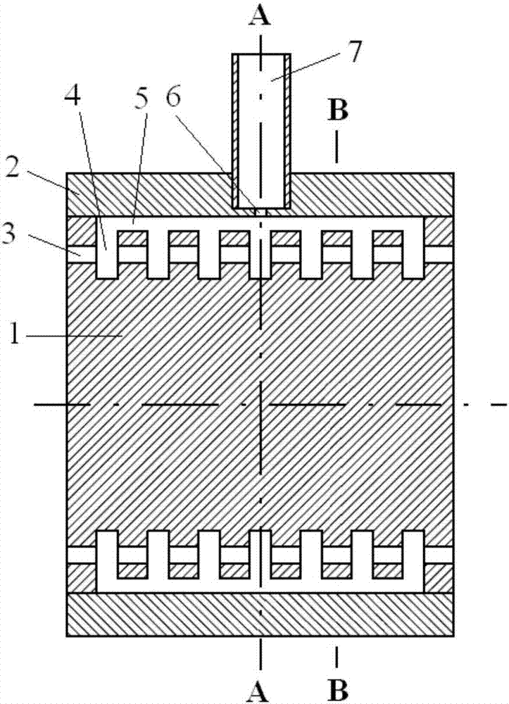
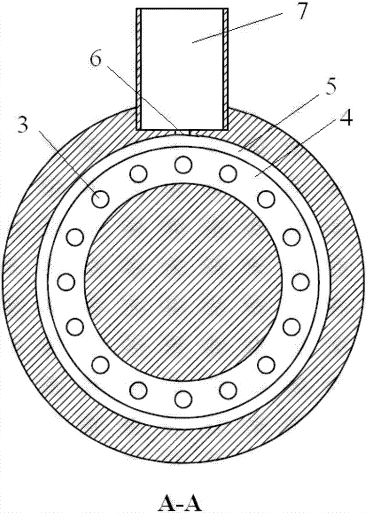
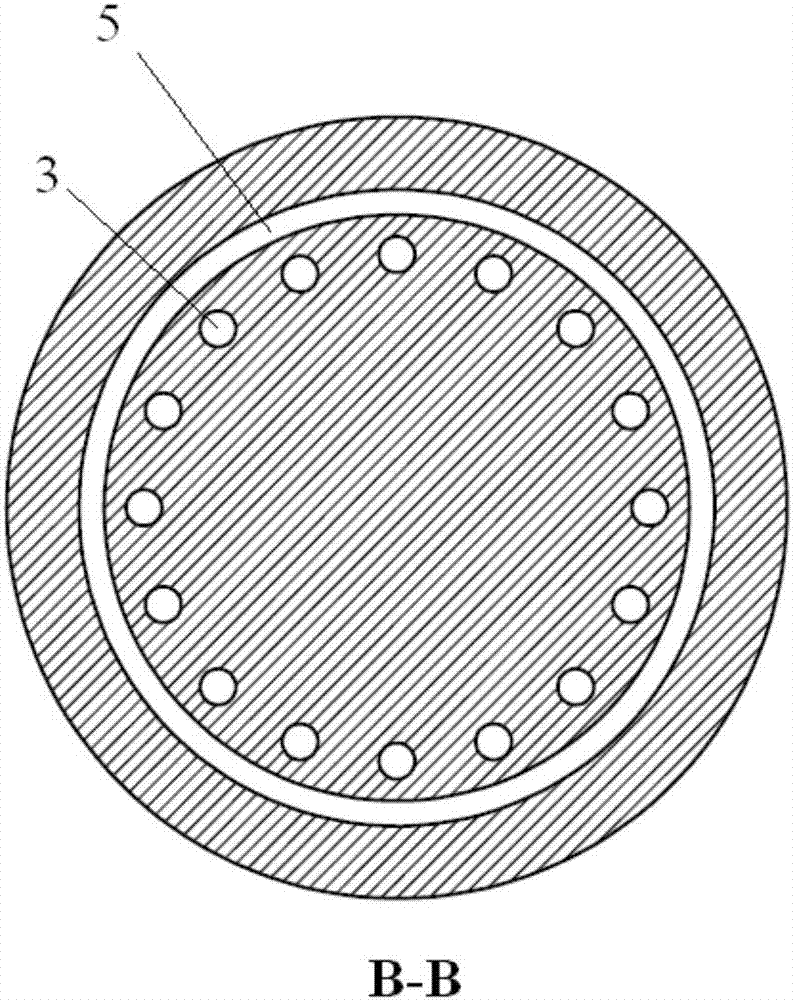
[0012] In this embodiment, the working frequency is 94GHz (the corresponding working wavelength λ is about 3.2mm), the working voltage is 20kV, and the working is in the fundamental mode (TM 010 Take the extended interaction device in the mode) state as an example:

[0013] The nominal diameter of the core 1 is Φ8.7mm, the axial length is 8.0mm, the nominal inner diameter of the shell 2 is also Φ8.7mm, the outer diameter is Φ12mm, and the axial length is 8.0mm, and the material is oxygen-free copper; In this embodiment, 7 annular resonators 4 are arranged on the core body 1, and the inner and outer radii of each annular resonator are respectively R2.4mm, R4.0mm (that is, the radial height of the resonator is 1 / 2λ), the axial width of each annular resonant cavity is 0.40mm, the distance between two adjacent resonant cavities is 0.52mm, the axial length of the ring-shaped coupling channel 5 is 5.92mm, and the inner and outer radii are R4. 0mm, R4.35mm (that is, the radial clea...


PUM


Abstract

The invention belongs to a millimeter wave expansion interaction device in a vacuum electronic device. The millimeter wave expansion interaction device comprises a device body which consists of a shell and a core body, an annular barrel-type coupling channel, circular annular resonant cavities and electron beam channels, output waveguide and coupling holes. The millimeter wave expansion interaction device adopts the cylindrical body and the circular annular resonant cavities which are formed around the axis of the core body in parallel at intervals; the lengths of inner circumference and outer circumference of the resonant cavities are far greater than working wavelengths; 5-19 resonant cavities and 5-20 electron beam channels can be set, and the lengths of the device can be greatly shortened, so that impedance, power capacity and output power of the device can be effectively improved; by means of controlling the radial dimensions of each resonant cavity to be within a range of 2 / 5-3 / 5<lambda> of the working wavelengths <lambda>, the long-term stable operation of the device in base mode state can be ensured; and therefore, the millimeter wave expansion interaction device has the characteristics of capability of improving output power of the device in a base mode state and working performance stability of the device, simple structure, simple and convenient production process, low production cost, long working service life and the like.

Description

technical field [0001] The invention belongs to an extended interaction device in a vacuum electronic device, in particular to a millimeter wave extended interaction device using a coaxial resonant cavity and multiple electron beams, the millimeter wave extended interaction device can be effective and stable in the fundamental mode state work. Background technique [0002] At present, the output power of the millimeter-wave source based on vacuum electron technology is mainly restricted by two aspects: one is that with the increase of the operating frequency, the structural size of the fundamental-mode working device is getting smaller and smaller, which limits the available power of the millimeter-wave device. The increase of the electron injection current also lowers its output power; for example, the patent document with the publication number CN1234623A discloses a multi-injection klystron filter loading broadband output circuit. Since it works in the fundamental mode, t...

Claims


Application Information

Patent Timeline
Patent Type & Authority Applications(China)
IPC IPC(8): H01J25/11H01J23/36
CPCH01J23/36H01J25/11G02F1/0356H01J23/20G02B6/12016H01P5/107H01Q9/0421
Inventor 蒙林王彬殷勇李海龙
Owner UNIV OF ELECTRONICS SCI & TECH OF CHINA
Why Eureka
Try Eureka