Solid waste incineration treatment system

A disposal system and solid waste technology, applied in the direction of incinerators, combustion methods, combustion types, etc., can solve the problems of unstable use and high cost, achieve stable operation, improve disposal efficiency, and reduce disposal costs

Pending Publication Date: 2017-10-20
无锡绿麦环保科技有限公司
View PDF6 Cites 8 Cited by
  • Summary
  • Abstract
  • Description
  • Claims
  • Application Information

AI Technical Summary

Problems solved by technology

Therefore, a nitrogen generating device or nitrogen filling is generally designed for protection, but both the nitrogen generating device and the nitrogen filling are extremely expensive, and the use is unstable

Method used


Image

  • Solid waste incineration treatment system
  • Solid waste incineration treatment system
  • Solid waste incineration treatment system

Examples


Embodiment 1

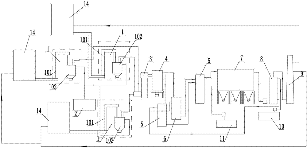
[0031] Embodiment 1: as figure 1 As shown, the solid waste incineration disposal system of this embodiment includes a solid waste crushing device 14, a waste feeding device 13, a dry distillation device 1, a secondary combustion chamber 3, a waste heat boiler 4, a rapid cooling tower 5, and a neutralization tower connected in sequence. 6. Bag dedusting device 7, washing tower 8 and chimney 9, retort furnace 1 and waste heat boiler 4 are all connected to softening water device 2, washing tower 8 is connected to lye pool 10, and neutralization tower 6 is connected to lime slurry pool 11. In this incineration system, the waste flue gas treatment process includes a semi-dry deacidification process and a wet deacidification process. The semi-dry deacidification process includes introducing the lime slurry in the lime slurry pool 11 into the neutralization tower 6 and The reaction process of the acid gas in the flue gas, the wet deacidification includes the reaction process of passi...

Embodiment 2

[0033] Embodiment 2: This embodiment has been improved on the basis of Embodiment 1, and the washing tower 8 is connected with the quenching tower 5 through pipelines, and the residual lye, salt, etc. of the washing tower 8 are transported to the quenching tower 5 by delivery equipment . The treatment process of this embodiment also includes a semi-dry deacidification process and a wet deacidification process. The semi-dry deacidification process includes introducing the lime slurry in the lime slurry pool 11 into the neutralization tower 6 to mix with the acid gas in the flue gas. The reaction process of wet deacidification includes and the reaction process of passing the lye in the lye pool 10 into the scrubber and the acid gas in the flue gas; The lye and the salt produced are introduced into the quench tower 5. Since the residual lye is introduced into the quenching tower 5, on the one hand, it is used to enhance the quenching effect of the quenching tower 5, and on the o...

Embodiment 3

[0034]Embodiment 3: This embodiment is further improved on the basis of Embodiment 2. Two sets of quenching towers 5 are arranged. The work can be switched among the towers 5 to realize one for use and one for standby. Since the residual lye and salt in the washing tower 8 are introduced into the quenching tower 5, the salt content in the quenching tower 5 increases. In order not to affect the work effect, the quenching tower 5 needs to be desalted regularly, and the desalination needs to be shut down. Therefore, two sets of quenching towers 5 are used for switching to realize continuous operation. The treatment process of this embodiment includes a semi-dry deacidification process and a wet deacidification process. The semi-dry deacidification process includes introducing the lime slurry in the lime slurry pool 11 into the neutralization tower 6 and the acid gas in the flue gas. The reaction process, wet deacidification includes and the reaction process of passing the lye in...


PUM


Abstract

The invention relates to a solid waste incineration treatment system. The system comprises a waste feeding device, a dry distillation device, a two-combustion form, an afterheat boiler, a quench tower, a neutralizing tower, a cloth bag dust removing device, a washing tower and a chimney; a dry distillation furnace and the afterheat boiler are both connected with a soft water device; the washing tower is connected with an alkali liquid pool; and the neutralizing tower is connected with a lime slurry pool. The semi-dry process deacidification is adopted to combine with the wet process deacidification; on the one hand, zero emission of nitrogen phosphorus after the tail gas treatment can be guaranteed; and on the other hand, generation of a lot of salt in the quench tower is prevented, and the cleaning period is prolonged.

Description

technical field [0001] The invention relates to the technical field of solid waste treatment, in particular to a solid waste treatment system. Background technique [0002] With the rapid development of social economy and the improvement of people's consumption level, the amount of industrial solid waste generated in the production process of enterprises is increasing day by day. Industrial solid waste, especially hazardous waste, has the characteristics of serious, long-term, potential, irreversible and difficult to control the pollution of the ecological environment. If not handled properly, it will leave great hidden dangers to people's health, environment and economic development. [0003] At present, many regions in my country have built or are planning to build waste centralized treatment and disposal centers, including comprehensive utilization, incineration, physical chemical, stabilization / solidification, safe landfill and other treatment of hazardous waste, and ha...

Claims


Application Information

Patent Timeline
Patent Type & Authority Applications(China)
IPC IPC(8): F23G5/033F23G5/16F23G5/44
CPCF23G5/033F23G5/16F23G5/44
Inventor 张莉朱泽峰
Owner 无锡绿麦环保科技有限公司
Why Eureka
Try Eureka