Fluidized bed hydrogenation reaction system and fluidized bed hydrogenation method

A technology of ebullated bed reactor and hydrogenation reaction, which is applied in chemical instruments and methods, chemical/physical processes, etc., can solve the problems of affecting the effect of hydrogenation reaction, affecting the effect of gas-liquid separation, and the amount of catalyst should not be too much, etc., to achieve Improve the effect of hydrogenation reaction, improve the volume utilization rate, and the effect of good separation effect

Active Publication Date: 2017-10-27
上海竣铭化工工程设计有限公司
View PDF9 Cites 6 Cited by
  • Summary
  • Abstract
  • Description
  • Claims
  • Application Information

AI Technical Summary

Problems solved by technology

[0003] There are currently two main types of ebullating hydrogenation technology, one is the oil phase circulation method, such as the ebullating bed process described in USRe25,770, the disadvantage of this process in practical application is: in order to maintain the liquid-solid separation effect, The amount of catalyst in the reactor should not be too much, and the utilization rate of the reactor is low. The utilization rate of the industrial ebullating bed reactor is generally only about 40% (the utilization rate generally refers to the percentage of the catalyst loading to the reactor volume (excluding the head space). The utilization rate of the reactor is generally more than 90%); the reactor has a large space because the residence time of the liquid material is too long without catalytic conditions, there is no hydrogenation reaction in this part, and the material is easy to react and coke at high temperature
Another kind is to arrange three-phase separator in the reactor, carry out gas-liquid-solid separation in the upper part of the reactor, as the ebullating bed reactor that CN02109404.7 introduces, by arranging built-in three-phase separator according to this scheme, can Increase the amount of catalyst, that is, increase the utilization space of the reactor, but in actual use, the increase in the amount of catalyst is limited. If the amount of catalyst increases, the separation effect of the three-phase separator will drop rapidly, and it is actually more efficient than the first type of ebullating bed reactor. The improvement of the efficiency is limited; the Chinese patent CN101721961B improves the above-mentioned patented technology. The upper section of the inner cylinder and the outer cylinder of the three-phase separator are both inverted cone-shaped structures, and the lower sections are cylindrical cylindrical structures, and internal components are arranged in the middle of the reactor. , the catalyst settlement in this patent is mainly concentrated near the cylinder wall. Although the internal components used are conducive to a more uniform radial velocity distribution of the fluid to a certain extent, the separation effect is poor, especially in large-scale elongation. The amount of catalyst added Very large, the carrying capacity of the catalyst is large
The Chinese patent CN101376092B has further improved the above-mentioned technology. A guiding structure is set along the cylinder wall at the lower part of the three-phase separator. Using the guiding structure, the operating flexibility of the three-phase separator is increased, the efficient separation of the three-phase separator is ensured, and the belting of the catalyst is reduced. output, increase the amount of catalyst storage, and increase the utilization rate of the reactor, but when in use, it is still necessary to set a catalyst dilute phase area in a certain area at the lower part of the three-phase separator (as shown in the attached figure, the amount of catalyst in this area is very small, basically no Hydrogenation reaction occurs), otherwise the separation effect of the three-phase separator still cannot meet the requirements, and the existence of the dilute phase zone affects the further improvement of the utilization rate of the reactor (although it is pointed out in the specification that the catalyst loading in the reactor cylinder can be 40% to 70% of the reactor volume, but generally only about 50% can operate stably), which also affects the hydrogenation reaction effect, and after the scale of the reactor is enlarged, it is more difficult to increase the catalyst loading, and it is difficult to reach the experimental level. The effect of the device
However, when the hydrogenation reaction product enters the hot high-pressure separator, the gas-liquid two-phase share one inlet, and the separation time is short, which affects the gas-liquid separation effect.

Method used


Image

  • Fluidized bed hydrogenation reaction system and fluidized bed hydrogenation method
  • Fluidized bed hydrogenation reaction system and fluidized bed hydrogenation method
  • Fluidized bed hydrogenation reaction system and fluidized bed hydrogenation method

Examples


Embodiment 1

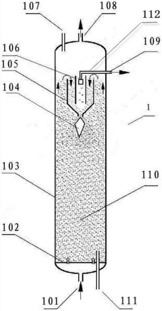
[0052] The ebullating bed reactor and the three-phase separator structure used in embodiment 1 are as follows figure 1 , The separation effect of the three-phase separator is simulated by the cold model. The size of the cold mold device is: the inner diameter of the reactor cylinder is 300mm, the height of the reactor cylinder is 3500mm, the height of the three-phase separator is 400mm, the diameter of the upper straight section of the outer cylinder of the three-phase separator is 200mm, the distance between the inner cylinder and the outer cylinder The distance between the annular gap is 80mm, the height difference between the upper end of the inner cylinder and the upper end of the outer cylinder is 60mm, the gap between the lower end opening of the inner cylinder and the contraction section of the outer cylinder is 60mm, the diameter of the lower opening of the contraction section of the outer cylinder is 90mm, and the outer cylinder The shrinkage angle of the lower frustu...

Embodiment 2

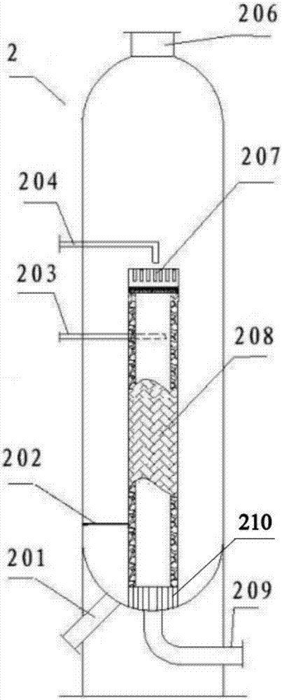
[0066] according to figure 2 Structural design of thermal high-pressure separator to simulate gas-liquid separation operation under filtration conditions. The pressure is 10MPa, the temperature is 270°C, and the liquid phase is residual oil at atmospheric pressure. Prepare catalyst solid powder with a content of 15 μg / g below 100 mesh (100 mesh sieve), and the filtration accuracy of the filter cartridge is designed to be 30 mesh. Nitrogen, the gas-liquid volume ratio is 600:1, and the filtration strength is 3600Kg / (m2 filter material·hour). After 2000 hours of operation, the pressure drop (the difference between the gas phase pressure and the liquid outlet pressure) of the hot high-pressure separator normally increased (compared to the initial value) by 3.7%, and the filtration capacity did not decrease. It is expected to be able to operate stably for 2 to 3 years.

Embodiment 3

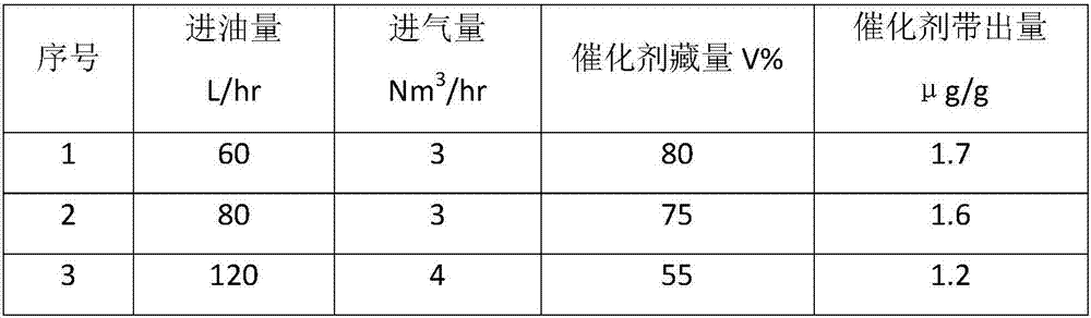
[0070] Coal tar hydrogenation test was carried out by using the fluidized bed hydrogenation method of the present invention. Described ebullating bed reactor and three-phase separator are by the conditions described in embodiment 1, and described heat high pressure separator is by the conditions described in embodiment 2, the gas phase outlet 108 of ebullating bed reactor and the gas phase inlet of heat high pressure separator 203 is connected, and the liquid phase outlet 109 of the ebullated bed reactor is connected with the liquid phase inlet 204 of the hot high-pressure separator. The hydrogenation catalyst used in the test is an alumina microsphere catalyst with a particle size of 1.5 mm, and the catalyst storage (calculated at rest) is 75% of the effective volume of the reactor (excluding the head space). The reaction pressure of the ebullated bed reactor is 15MPa, the reaction temperature is 410°C (in the middle of the reactor), and the volume space velocity of the raw m...


PUM


Abstract

The invention relates to a fluidized bed hydrogenation reaction system, which comprises a fluidized bed reactor, wherein the fluidized bed reactor comprises a reactor barrel; a three-phase separator is arranged at the upper part of the reactor barrel and comprises an inner barrel and an outer barrel; openings are formed in the upper ends and the lower ends of the inner barrel and the outer barrel; the opening in the upper end of the outer barrel is lower than that of the inner barrel and the opening in the lower end of the outer barrel is lower than that of the inner barrel; the inner barrel is a straight barrel segment; the straight barrel segment is arranged at the upper part of the outer barrel and a frustum-shaped contraction segment is arranged at the lower part; the opening in the lower end of the contraction segment is the opening in the lower end of the outer barrel; and a gap is arranged between the opening in the lower end of the inner barrel and the outer barrel contraction segment, so that a material passes through the gap. The fluidized bed hydrogenation reaction system is adopted by the fluidized bed hydrogenation method, so that the utilization rate (namely the catalyst inventory in the reactor) of the reactor is further improved, and the hydrogenation reaction effect can be further improved.

Description

technical field [0001] The invention belongs to the technical field of hydrogenation, and in particular relates to a fluidized bed hydrogenation reaction system and a fluidized bed hydrogenation method. Background technique [0002] Ebullated bed hydrogenation reaction refers to the process of hydrogenation reaction of feedstock oil (mainly in liquid phase) and hydrogen (gas phase) on catalyst (solid phase). Hydrogenation reaction mainly occurs in hydrodesulfurization, hydrodenitrogenation and hydrodeoxygenation , hydrogenation saturation, hydrocracking, etc. The reactor operates in the boiling state of gas, liquid and solid. The catalyst is in a boiling state driven by the raw material oil and hydrogen entering from the bottom of the reactor, which is in a completely different fluid state from the fixed bed reactor. The ebullating bed hydrogenation reaction can process low-quality feed oil with high metal and high asphaltene content. The reaction has the characteristics of...

Claims


Application Information

Patent Timeline
Patent Type & Authority Applications(China)
IPC IPC(8): B01J8/18B01J8/22
CPCB01J8/1854B01J8/1872B01J8/224B01J2208/00539B01J2208/00769B01J2219/00004
Inventor 王小英
Owner 上海竣铭化工工程设计有限公司
Why Eureka
Try Eureka