Multi-cathode-compartment denitrifying phosphorus removal electrogenesis device by activated sludge process

A technology of denitrification phosphorus removal and activated sludge method, which is applied in the field of denitrification phosphorus removal power generation device in multiple cathode chambers of activated sludge method, can solve the problems of waste of organic energy, reduce operating costs, reduce equipment capacity, reduce The effect of occupying land

Pending Publication Date: 2017-11-21
SHENYANG JIANZHU UNIV ARCHITECTURE DESIGNING INST
View PDF5 Cites 3 Cited by
  • Summary
  • Abstract
  • Description
  • Claims
  • Application Information

AI Technical Summary

Problems solved by technology

[0003] In view of the above-mentioned technical problems, in order to overcome the waste of a large amount of organic energy in the process of sewage treatment and the lack of renewable green energy, and to improve the existing MFC coupling power generation process, the present invention provides an activated sewage Sludge method multi-cathode chamber denitrification and phosphorus removal power generation device, which can not only reduce the concentration of COD, TN and TP in sewage to purify sewage, but also make more extensive use of electron acceptors to generate electricity

Method used


Image

  • Multi-cathode-compartment denitrifying phosphorus removal electrogenesis device by activated sludge process
  • Multi-cathode-compartment denitrifying phosphorus removal electrogenesis device by activated sludge process

Examples


Embodiment

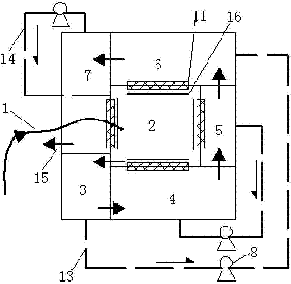
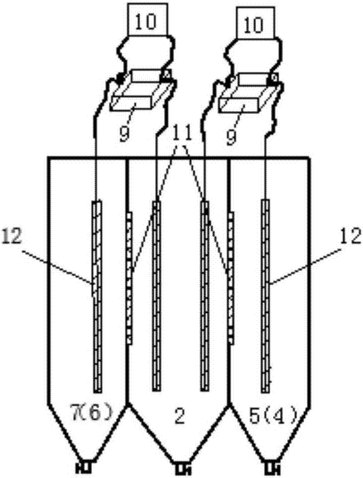
[0021] Example: such as figure 1 As shown, the present invention includes an anaerobic tank 2, a primary sedimentation tank 3, an aerobic tank 4, a secondary sedimentation tank 5, an anoxic tank and a final sedimentation tank 7, which are connected in sequence, wherein the anaerobic tank 2 serves as the anode chamber of the microbial fuel cell The aerobic tank 4, the secondary sedimentation tank 5, the anoxic tank 6 and the final sedimentation tank 7 are used as the cathode chambers of the microbial fuel cell and are arranged around the anaerobic tank. The anode chamber and the cathode chamber are respectively connected with a resistor 9, and the anaerobic tank 2 Proton exchange membrane 11 is installed between the aerobic tank 4, the secondary sedimentation tank 5 and the anoxic tank 6. The primary sedimentation tank 3 and the anoxic tank 6 are connected by a sludge exceeding pipeline 13, and the aerobic tank 4 and the secondary sedimentation tank The tank 5, the final sediment...


PUM


Abstract

The invention discloses a multi-cathode-compartment denitrifying phosphorus removal electrogenesis device by an activated sludge process, and belongs to the technical field of sludge treatment. The electrogenesis device comprises an anaerobic pool, a primary settling tank, an aerobiotic pool, a secondary sedimentation tank, an oxygen deficit pool and a final sedimentation tank, wherein the anaerobic pool is used as an anode compartment of a microbial fuel cell; the aerobiotic pool, the secondary sedimentation tank, the oxygen deficit pool and the final sedimentation tank are used as a cathode compartment of the microbial fuel cell and arranged around four sides of the anaerobic pool; the anode compartment and the cathode compartment are externally connected with resistors, and four pool walls of the anaerobic pool are equipped with proton exchange membranes. The anaerobic pool and the aerobiotic pool, the secondary sedimentation tank, the oxygen deficit pool and the final sedimentation tank are separated by the proton exchange membranes, and the proton exchange membranes can be freely opened and closed by a baffle. The primary settling tank is connected with the oxygen deficit pool through a surpass sludge pipeline, and the aerobiotic pool and the secondary sedimentation tank, the final sedimentation tank and the anaerobic pool are connected through backflow sludge pipelines; a water outlet pipeline and a sludge discharge opening are arranged on the final sediment tank; when the sludge is treated, power energy is generated. The multi-cathode-compartment denitrifying phosphorus removal electrogenesis device can effectively reduce the concentration of COD, TP and TN in sewage, and generate stable voltage value by widely using an electron acceptor.

Description

Technical field [0001] The invention belongs to the technical field of sewage treatment, and in particular relates to an activated sludge process multi-cathode chamber denitrification and denitrification and dephosphorization power generation device, which can process COD, nitrogen, phosphorus and other pollutants in sewage while generating electricity. Background technique [0002] The traditional denitrification process for phosphorus removal is mainly composed of anaerobic, aerobic and anoxic reactors, which are divided into single sludge process and double sludge process. In the single sludge process, nitrifying bacteria and denitrifying phosphorus accumulating bacteria exist in the same reactor, and they experience three operating environments: anaerobic, anoxic, and aerobic. However, in the double sludge process, nitrifying bacteria Denitrifying bacteria each exist in a separate reactor, they can grow in their optimal operating environment, and can better solve the competit...

Claims


Application Information

Patent Timeline
Patent Type & Authority Applications(China)
IPC IPC(8): C02F3/00C02F3/30C02F3/34H01M8/16
CPCH01M8/16C02F3/005C02F3/308C02F3/34C02F2203/006C02F2209/08C02F2209/16C02F2301/046Y02E60/50
Inventor 张立成王文强
Owner SHENYANG JIANZHU UNIV ARCHITECTURE DESIGNING INST
Why Eureka
Try Eureka