A low-temperature evaporation treatment system for desulphurization waste water

A treatment system and desulfurization wastewater technology, applied in the field of low-temperature flash evaporation treatment system, can solve the problems of insufficient operation safety and stability, high operating cost of filtration reduction method, etc., so as to avoid secondary pollution and adapt to the new strength with low load , the effect of low operating cost

Active Publication Date: 2017-12-15
UNI RISING BEIJING TECH CO LTD
View PDF6 Cites 7 Cited by
  • Summary
  • Abstract
  • Description
  • Claims
  • Application Information

AI Technical Summary

Problems solved by technology

However, the operating cost of the membrane technology filtration reduction method is relatively high, and its operation safety and stability are insufficient

Method used


Image

  • A low-temperature evaporation treatment system for desulphurization waste water
  • A low-temperature evaporation treatment system for desulphurization waste water

Examples


Embodiment 1

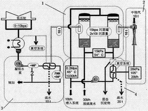
[0041] Such as figure 1 As shown, it is aimed at water-cooled units in thermal power plants. The desulfurization wastewater low-temperature evaporation treatment system includes a wastewater heating system, a wastewater flash treatment system, a flash steam cooling system, and a wastewater heating heat source system.

[0042] The upper part of the first flash tank and the second flash tank is equipped with a spray flash mechanism, and the lower part is a desulfurization wastewater tank, and the intermediate space forms a flash working area. An opening is set on the tank body of the flash working area of ​​the first flash tank, which is connected to the first condenser through a pipeline, and an opening is set on the tank body of the flash working area of ​​the second flash tank, which is connected to the first condenser through a pipeline. Turbocharger suction port. The wastewater outlet of the desulfurization device is connected to the first flash tank and the second flash ...

Embodiment 2

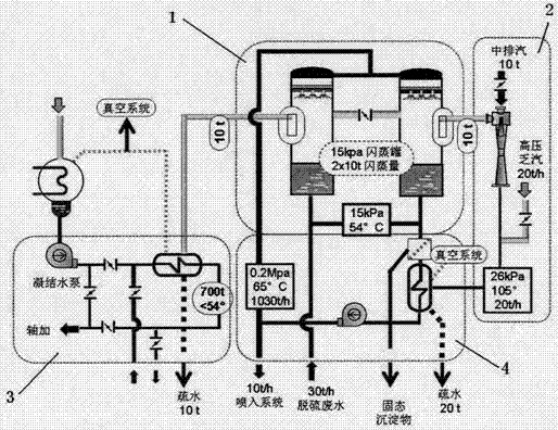
[0051] Such as figure 2 As shown, it is aimed at air-cooled units in thermal power plants (or high back pressure operation of water-cooled steam turbines).

[0052] The difference between this implementation case and Example 1 lies in the setting of the waste water heating heat source system. For thermal power plant air-cooled units or water-cooled steam turbines operating at high back pressure, the steam in the wastewater heating system can also be boosted and heated without passing through the injector, and directly connected to the pipeline to use the normal high back pressure operation of the air-cooled steam turbine or the high back pressure of the water-cooled steam turbine After operation, the exhaust steam (exhaust steam) of the steam turbine, as a heat source, enters the heating condenser to heat the waste water.


PUM


Abstract

A low-temperature evaporation treatment system for desulphurization waste water is disclosed. The system includes a waste water heating system, a waste water flash evaporation system, a flash evaporation steam cooling system, and a waste water heating source system. The desulphurization waste water in the waste water flash evaporation system flows through the waste water heating system and is heated, and then the waste water enters a spraying flash evaporation mechanism of the waste water flash evaporation system and is subjected to flash evaporation. Flash evaporation steam of the waste water flash evaporation system is distributed into two pipelines respectively connected to the flash evaporation steam cooling system and the waste water heating source system. The waste water heating source system provides heated steam for the waste water heating system. A desulphurization waste water circulating pipeline in the waste water flash evaporation system is connected to a flue spraying and evaporation system through a concentrated-water discharging pipe. The desulphurization waste water is subjected to heating and low-temperature flash evaporation to reduce the amount, thus achieving zero emission of the desulphurization waste water, improving running safety of an electrostatic precipitator and recovering salt-free water that is obtained through flash evaporation.

Description

technical field [0001] The invention belongs to the field of water treatment, and relates to a low-temperature flash evaporation treatment system for desulfurization (or salt-containing) waste water. Background technique [0002] In order to meet the national requirements for ultra-low SO2 emissions, domestic power plants or other coal-fired equipment mostly adopt limestone-gypsum wet flue gas desulfurization technology, which produces serious wastewater discharge while desulfurizing efficiently. In April 2015, the State Council issued the "Water Pollution Action Plan" to strengthen the prevention and control of various types of water pollution. Due to the complex composition of desulfurization wastewater (including suspended solids, fluoride, heavy metals and salt, etc.) highly anticipated. [0003] At present, most of the desulfurization wastewater treatment adopts the process of chemical precipitation (traditional three-box method) to remove desulfurization wastewater po...

Claims


Application Information

Patent Timeline
Patent Type & Authority Applications(China)
IPC IPC(8): C02F1/06C02F1/02C02F103/18
CPCC02F1/02C02F1/048C02F1/06C02F2103/18
Inventor 林咸钗
Owner UNI RISING BEIJING TECH CO LTD
Why Eureka
Try Eureka