Honeycomb type low-temperature denitration method and device thereof

A low-temperature denitrification, honeycomb technology, applied in the direction of separation methods, chemical instruments and methods, metal/metal oxide/metal hydroxide catalysts, etc., can solve the problem that the simulation effect is different from the actual use situation, and cannot be evaluated very well Denitrification catalysts, unfavorable industrialization of denitrification catalysts, etc., to achieve the effects of avoiding poisoning, short preparation cycle and stable efficiency

Pending Publication Date: 2018-03-30
SHIHEZI UNIVERSITY
View PDF7 Cites 5 Cited by
  • Summary
  • Abstract
  • Description
  • Claims
  • Application Information

AI Technical Summary

Problems solved by technology

[0002] Existing laboratory simulated flue gas denitrification devices are limited to powdered catalysts, the loading amount is milligram level, and the carrier gas is inert gas or nitrogen, and water vapor is brought in by the carrier gas, which is quite different from the actual denitrification process of the power plant, and the simulation effect There is a discrepancy with the actual use, and the denitrification catalyst cannot be well evaluated, which is not conducive to the industrialization of the denitrification catalyst

Method used


Image

  • Honeycomb type low-temperature denitration method and device thereof
  • Honeycomb type low-temperature denitration method and device thereof
  • Honeycomb type low-temperature denitration method and device thereof

Examples


Embodiment 1

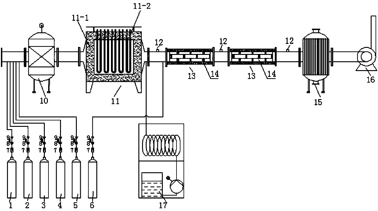
[0044] Catalyst activity evaluation Catalyst usage is 4 pieces of 100mm×100mm×150mm honeycomb cordierite-based catalysts, reacted in a fixed bed reactor, the flow rate is controlled by a mass flow meter, and the reaction conditions are [NH 3 ] / [NO]=1, the amount of NO is 200ppm, NH 3 =200ppm, the flow rate is 10m 3 / h. The test is carried out according to the following temperature gradient, and the specific data are as follows:

[0045] temperature °C

Embodiment 2

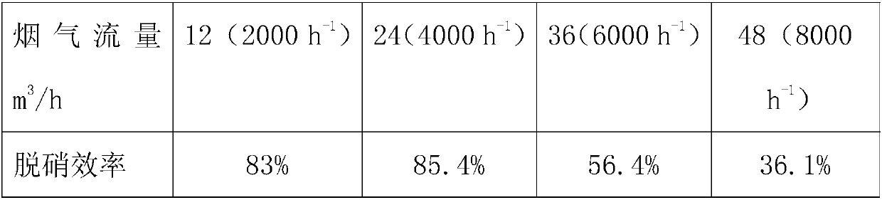
[0047] Catalyst activity evaluation Catalyst usage is 4 pieces of 100mm×100mm×150mm honeycomb cordierite-based catalysts, reacted in a fixed bed reactor, the flow rate is controlled by a mass flow meter, and the reaction conditions are [NH 3 ] / [NO]=1, the amount of NO is 200ppm, NH 3 = 200ppm. At a temperature of 100°C, by changing the flue gas flow rate to change the space velocity, the flue gas flow rate changes as the following gradient, and the results are as follows:

[0048]

Embodiment 3

[0050] Catalyst activity evaluation Catalyst usage is 4 pieces of 100mm×100mm×150mm honeycomb cordierite-based catalysts, reacted in a fixed bed reactor, the flow rate is controlled by a mass flow meter, the reaction conditions are temperature 100°C, the amount of NO is 200ppm, and the flow rate is 10m 3 / h,. Change [NH 3 ] / [NO] ratio, the NO removal rate was determined by the flue gas analyzer. Five data were measured at intervals under each condition. The result is as follows:

[0051] [NH 3 ] / [NO]


PUM

PropertyMeasurementUnit
pore sizeaaaaaaaaaa

Abstract

The invention relates to a honeycomb type low-temperature denitration method and device thereof. The method comprises the following specific steps: mixing oxygen, nitrogen, carbon dioxide, carbon monoxide gas and nitrogen monoxide gas according to certain proportion, and preheating; mixing the preheated gas mixture with an ammonia gas according to certain proportion, and enabling the mixed gas topass through a fixed bed reactor with a honeycomb type catalyst according to certain flow rate, so as to realize catalytic denitration treatment; finally, cooling the treated gas and discharging through a tail gas fan. By adopting the technical scheme, the method provided by the invention, in which impregnation coating is applied, has the advantages of simple technology, low energy consumption and perfect application prospect. After being loaded with a catalyst, the specific surface area of honeycomb cordierite is remarkably increased, and the active components are uniformly distributed on the carrier surface. Through shaking treatment, the active components are tightly combined with the carrier. Meanwhile, the raw materials of the Mn-CeO2 / Al2O3 catalyst are easily available without toxicand harmful effects, and the preparation cycle is relatively short.

Description

technical field [0001] The invention relates to a honeycomb low-temperature denitrification method and a device thereof. Background technique [0002] Existing laboratory simulated flue gas denitrification devices are limited to powdered catalysts, the loading amount is milligram level, and the carrier gas is inert gas or nitrogen, and water vapor is brought in by the carrier gas, which is quite different from the actual denitrification process of the power plant, and the simulation effect There is a discrepancy with the actual use, and the denitration catalyst cannot be well evaluated, which is not conducive to the industrialization of the denitration catalyst. Contents of the invention [0003] In order to solve the above problems, the object of the present invention is to provide a method with simple process, low energy consumption and good stability. And pass into SO 2 、H 2 A honeycomb low-temperature denitrification method and device thereof with a stable efficienc...

Claims


Application Information

Patent Timeline
Patent Type & Authority Applications(China)
IPC IPC(8): B01D53/90B01D53/56B01J23/34
CPCB01D53/8628B01D53/90B01J23/34B01D2251/2062B01D2255/2073B01D2255/2065B01D2255/2092
Inventor 曹鹏赵勇刚张诚王成志
Owner SHIHEZI UNIVERSITY
Why Eureka
Try Eureka