
Snapshot imaging spectrometer based on miniature imaging lens array and stepped phase reflector

An imaging spectrometer and mirror technology, which is used in spectrometry/spectrophotometry/monochromator, instruments, scientific instruments, etc., to achieve the effects of fast detection speed, high integration and strong stability

Active Publication Date: 2018-06-19
CHANGCHUN INST OF OPTICS FINE MECHANICS & PHYSICS CHINESE ACAD OF SCI
View PDF3 Cites 5 Cited by
  • Summary
  • Abstract
  • Description
  • Claims
  • Application Information

AI Technical Summary

Problems solved by technology

[0004] In order to solve the problem of real-time acquisition of three-dimensional data cube and miniaturization of imaging spectrometer in existing traditional imaging spectrometer, the present invention provides a snapshot imaging spectrometer based on micro imaging mirror array and stepped phase reflector

Method used


Image

  • Snapshot imaging spectrometer based on miniature imaging lens array and stepped phase reflector
  • Snapshot imaging spectrometer based on miniature imaging lens array and stepped phase reflector
  • Snapshot imaging spectrometer based on miniature imaging lens array and stepped phase reflector

Examples


Embodiment 1

[0074] Example 1: for Figure 8 The grid beam splitter shown in s is manufactured, and the material is a double-sided polished (100) single crystal silicon wafer with high flatness and high parallelism. Its preparation method is:

[0075] 1. Growth or evaporation of silicon dioxide and silicon nitride and other dielectric films or composite films on the cleaned double-sided polished single crystal silicon surface as a masking film;

[0076] 2. Directional photolithography to expose the side groove pattern, and remove the masking film in the side groove pattern by etching to expose the surface of the single crystal silicon. Use single crystal silicon anisotropic etching solution to etch the side groove, and the etching depth is equal to the final thickness of the beam splitter window; the shape of the side groove can also be formed by arranging multiple rectangles or squares at a certain distance apart from the figure shown in the figure.

[0077] 3. Perform a second photolit...

Embodiment 2

[0079] Embodiment 2: For both horizontal and vertical grid rib structures Figure 9 The double-sided grating beam splitter of f can be manufactured by the above method, the difference is that it is necessary to prepare a double-sided masking film, which is realized by double-sided photolithography and double-sided etching, and the upper and lower surface patterns are the same. In the first photolithographic etching, the sum of the etching depths of the upper and lower surface side grooves is the final thickness value of the beam splitter window.

Embodiment 3

[0080] Example 3: For a grid beam splitter with a structure such as Figure 8 The shape of k is made, and the material is a double-sided polished silicon wafer with high flatness and high parallelism. Its production process is as follows:

[0081] 1. Evaporating aluminum film or thermally grown silicon dioxide or evaporating silicon nitride and other metal films or dielectric films or composite films on the cleaned double-sided polished single crystal silicon surface as a masking film;

[0082] 2. Photolithography to expose the side groove pattern, and remove the masking film in the side groove pattern by etching to expose the surface of the single crystal silicon. Using ICP or RIE technology for side grooves, the corrosion depth is equal to the final thickness of the beam splitter window; besides the figure shown, the shape of the side grooves can also be formed by multiple rectangles, squares, circles, ellipses or other polygonal shapes arranged at a certain distance. to m...


PUM


Abstract

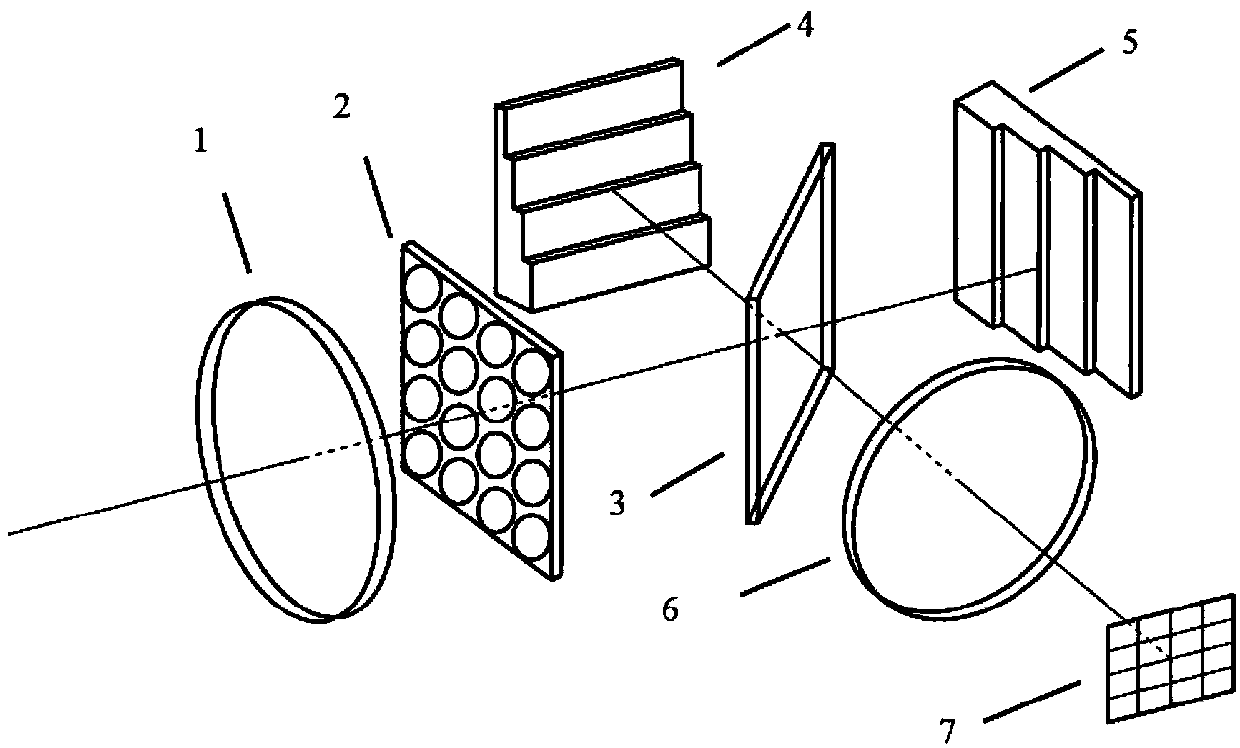
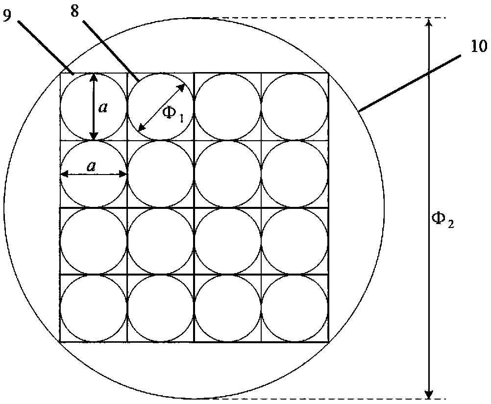
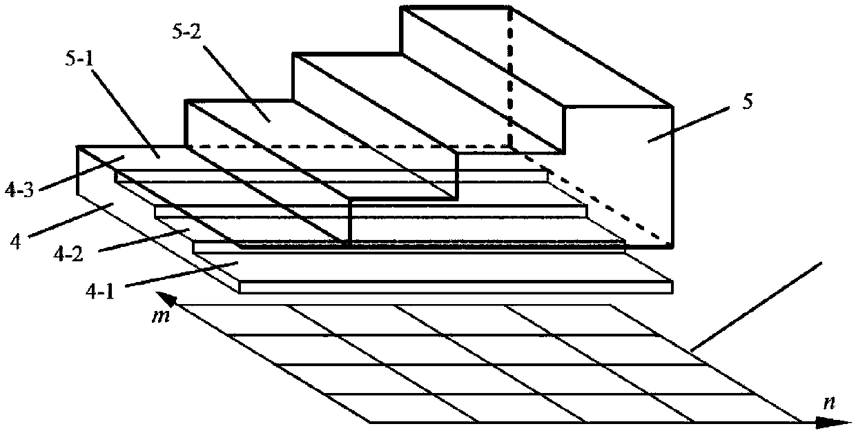
The invention discloses a snapshot imaging spectrometer based on a miniature imaging lens array and a stepped phase reflector, relates to the technical field of infrared imaging spectrum detectors, and solves problems of the real-time obtaining of a three-dimensional data cube and the miniaturization of an imaging spectrometer. The imaging spectrometer comprises a collimating mirror, the miniatureimaging lens array, a beam splitter, a lateral stepped phase reflector, a longitudinal stepped phase reflector, a relay imaging mirror, and an area array detector. The miniature imaging lens array isused for the multiple imaging of a target scene, and the imaging spectrometer which is used for the distributed phase modulation of multiple image fields through the stepped phase reflectors is employed. Through the light field coupling of a parallel imaging channel formed by the miniature imaging lens array and a parallel interference channel formed by the stepped phase reflectors, the imaging spectrometer achieves the multi-channel snapshot-type interference imaging of the target scene, does not need a complex movement mechanism, is small in size, is stationary, is high in stability, is high in integration degree, and is high in detection speed.

Description

technical field [0001] The present invention relates to a snapshot infrared interference imaging spectrometer in the technical field of infrared imaging spectrum detection instruments, in particular to a method that uses a micro-imaging mirror array for multiple imaging and uses stepped phase mirrors to perform distributed phase modulation on the light field of each imaging channel Multi-channel micro-snapshot infrared interferometric imaging spectrometer to achieve interference. Background technique [0002] Image features and spectral features are important means for people to identify substances. Effective detection of target image and spectral features can greatly improve people's ability to understand the world. Imaging feature detection is used to record the position and intensity information of objects, while spectral feature detection obtains wavelength-related information based on the emission, reflection, and transmission spectra unique to different substances. Wi...

Claims


Application Information

Patent Timeline
Patent Type & Authority Applications(China)
IPC IPC(8): G01J3/28G01J3/02
CPCG01J3/0208G01J3/2823
Inventor 梁静秋梁中翥孟德佳陶金吕金光王维彪秦余欣
Owner CHANGCHUN INST OF OPTICS FINE MECHANICS & PHYSICS CHINESE ACAD OF SCI
Learn More