
Flow reactor, device and method for electrochemically degrading volatile organic pollutants

A flow reactor, volatile organic technology, applied in chemical instruments and methods, separation methods, gas treatment, etc., can solve the problems of difficult material migration and conversion process, thick electrolyte solution, iron sludge precipitation, etc., to improve electrochemical devices , simple device, high degradation efficiency

Pending Publication Date: 2018-07-27
HOHAI UNIV
View PDF3 Cites 3 Cited by
  • Summary
  • Abstract
  • Description
  • Claims
  • Application Information

AI Technical Summary

Problems solved by technology

Since the anode of this patent uses Fe sheets, iron sludge will precipitate in the cathode-adsorbing conductive porous material after electrolysis for a long time, which is easy to block
Its electrolyte solution is thick, that is, the process of material migration and transformation of gas is difficult, the pressure used for aeration is high, and energy consumption is high.

Method used


Image

  • Flow reactor, device and method for electrochemically degrading volatile organic pollutants
  • Flow reactor, device and method for electrochemically degrading volatile organic pollutants
  • Flow reactor, device and method for electrochemically degrading volatile organic pollutants

Examples


Embodiment 1

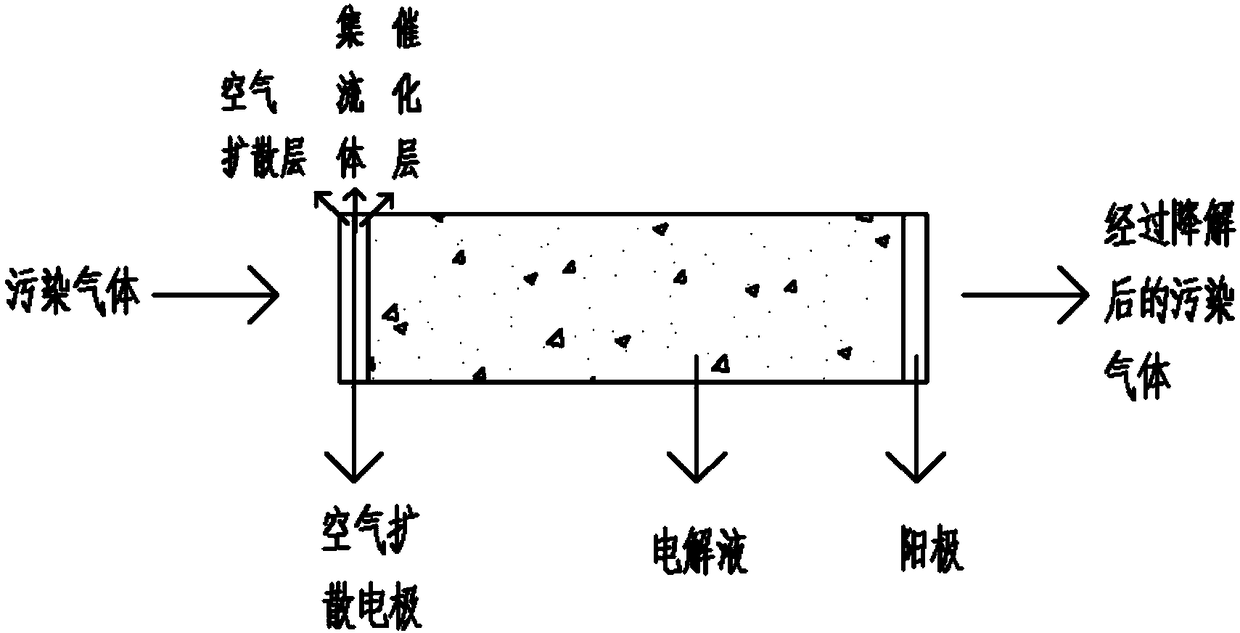
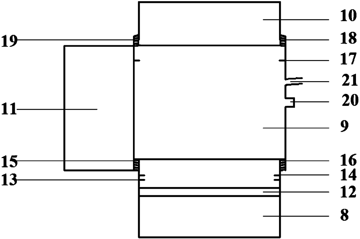
[0040] A flow reactor for the electrochemical degradation of volatile organic pollutants such as image 3 As shown, the flow reactor 4 is a cylindrical plexiglass body composed of four parts: an air inlet tank 8 , a housing 9 , an air outlet tank 10 , and a test tank 11 .

[0041] The air inlet tank 8 has an inner diameter of 3cm, an outer diameter of 4cm, and a height of 6cm. It is located at the bottom of the flow reactor. At 2-3 cm, there is a circle of partitions 13 and 14 with a width of 0.5 cm, the distance between the two partitions is 0.3 cm, and fastening clips are installed on the partitions, and there are external threads 15 at a distance of 1 cm from the top;

[0042] The housing 9 has an inner diameter of 3.4 cm, an outer diameter of 4.4 cm, and a height of 2 cm. It is located in the middle of the flow reactor, has no bottom and no cover, and has an internal thread 16 at a distance of 1 cm from the bottom, and a ring of partitions 17 at a distance of 2 to 3 cm from ...

Embodiment 2

[0052] The platinum sheet was used as the anode, the air diffusion electrode was used as the cathode, the gas blowing rate was 6L / h, and the electrolyte concentration was 0.8mol / L. The xylene removal rate was studied when the electrolysis voltage was 6-10V. The results are shown in Table 1.

[0053] Table 1

[0054]

[0055] It can be seen from Table 1 that the removal rate increases with the increase of voltage, and the removal rate is the largest at 10V. According to Faraday's law, when the current density increases, the output of the cathode and the electricity obtained by the anode also increase, resulting in HO and HO 2 ·、H 2 o 2 The amount of oxidant is more; therefore, the removal rate increases with the increase of current density. However, with the increase of voltage, the degree of polarization of the two poles increases, the energy consumption increases, the temperature of the electrolyte increases, and the decomposition rate of hydrogen peroxide will also acc...

Embodiment 3

[0057] The platinum sheet was used as the anode, the air diffusion electrode was used as the cathode, the electrolysis voltage was 10V, the electrolyte concentration was 0.8mol / L, and the xylene removal rate was studied when the air blowing rate was 4-8L / h. The results are shown in Table 2.

[0058] Table 2

[0059]

[0060] It can be seen from Table 2 that the removal rate increases with the increase of the blowing rate, and the removal rate is the largest when the blowing rate is 8L / h, but the removal rate slows down, mainly because more gaseous Pollutants add to the processing load.


PUM

PropertyMeasurementUnit
diameteraaaaaaaaaa
lengthaaaaaaaaaa

Abstract

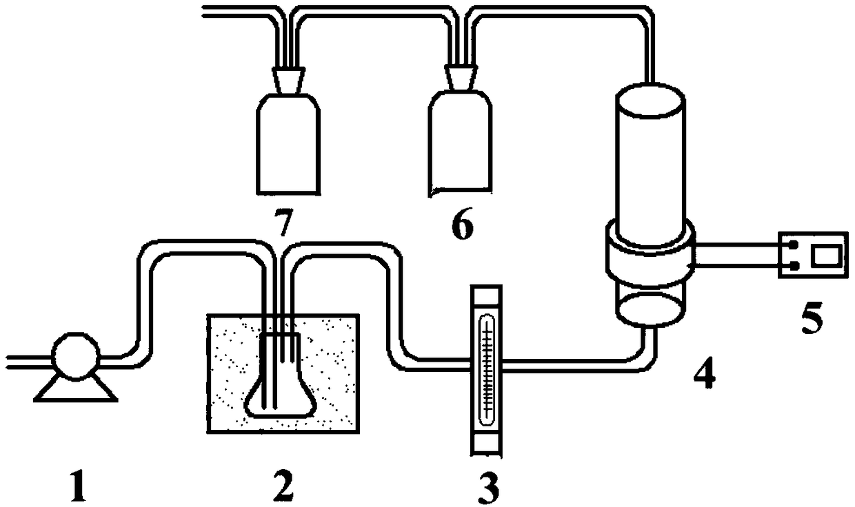
The invention discloses a flow reactor, a device and a method for electrochemically degrading volatile organic pollutants. The flow reactor is a hollow cylinder and comprises a gas inlet tank, a casing and a gas outlet tank sequentially from bottom to top; the gas inlet tank has a bottom surface and no cover, small holes for accommodating a gas inlet pipe are formed in the side wall, and a diaphragm type microporous air diffuser and a cathode air diffusion electrode are sequentially arranged above the small holes and in the gas inlet tank; the casing has no bottom or cover, and an anode platinum sheet with small holes is arranged at the top; the gas outlet tank has a cover and has no bottom, and a lead-out pipe is arranged at the top. The invention also discloses a device comprising the flow reactor and used for electrochemically degrading volatile organic pollutants and a method for electrochemically degrading volatile organic pollutants with the device. The device is simple and convenient to operate, cannot cause secondary pollution and can effectively degrade organic matter and the like.

Description

technical field [0001] The invention relates to a treatment method for volatile organic pollutants, in particular to a flow reactor for electrochemically degrading volatile organic pollutants, a device and a method thereof. Background technique [0002] Volatile organic compounds refer to a class of organic compounds that exist in the air in the form of steam at room temperature with a boiling point temperature of 50-260 °C and a saturated vapor pressure of more than 133.32 Pa at room temperature. They are also emitted by industries such as petrochemical, pharmaceutical, printing, and paint spraying. Most common gaseous pollutant. Depending on the humidity of the air condition, some of them will generate dry deposits (photochemical smog) and wet deposits (acid rain), endangering the ecological environment and human health. Formaldehyde, benzene, xylene, etc. are the main organic pollutants that exist indoors after decoration. They are toxic, highly carcinogenic, and genotox...

Claims


Application Information

Patent Timeline
Patent Type & Authority Applications(China)
IPC IPC(8): B01D53/32B01D53/86B01D53/44
CPCB01D53/32B01D53/8687B01D2255/806B01D2257/708
Inventor 祝建中季晖朱秋子陈靓徐迪
Owner HOHAI UNIV
Learn More