Novel electric control fuel oil system

A technology of fuel system and electronic control, which is applied in the direction of layout, container and packaging combined with the fuel supply of internal combustion engines, which can solve the problems of insufficient fueling smoothness, low resolution, inaccurate volume control and liquid level display, etc., and achieve overall The effect of compact structure design, improved performance and quality, and improved smoothness of refueling

Pending Publication Date: 2018-08-17
YAPP AUTOMOTIVE PARTS
View PDF0 Cites 7 Cited by
  • Summary
  • Abstract
  • Description
  • Claims
  • Application Information

AI Technical Summary

Problems solved by technology

[0006] The traditional fuel system has the following problems: 1) Refueling performance: Fuel enters the fuel tank through the fuel injection pipe. As the refueling progresses, the liquid level inside the fuel tank rises, and the steam inside the tank is discharged into the carbon tank through various valves and through the ventilation pipeline. When the oil level reaches the closing height of the liquid level control valve, the valve is closed due to the buoyancy of the liquid on the float inside the valve. At this time, the internal pressure of the fuel tank rises, and the fuel cannot be continuously injected, and the fuel gun jumps; After the gun jumps for the first time, the high-pressure gas inside the fuel tank is slowly discharged through the gravity valve. When the internal pressure of the fuel tank drops to a certain value, it can continue to refill. After adding a certain amount of fuel, the internal pressure of the fuel tank rises again, and the fuel gun jumps again. , and then repeat a certain number of refills to the full volume. Since the internal pressure of the fuel tank through the gravity valve releases slowly after the refueling gun jumps for the first time, due to the impact of liquid fuel during refilling, there will be back injection and back surge at the refue

Method used


Image

  • Novel electric control fuel oil system
  • Novel electric control fuel oil system
  • Novel electric control fuel oil system

Examples


Embodiment 1

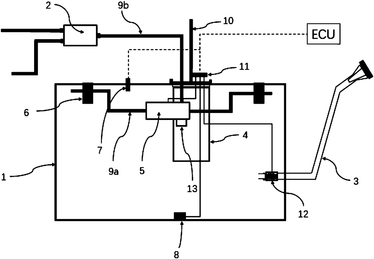
[0031] Embodiment 1: see figure 1, Figure 2, a new electronically controlled fuel system, the fuel system includes a fuel tank body 1, a carbon tank 2, a fuel injection pipe 3, a fuel pump 4, an electronically controlled exhaust valve 5, a vent 6, an air pressure sensor 7, and a liquid level sensor 8. Ventilation pipeline 9, oil supply / return pipeline 10, control unit 11, and electronically controlled check valve 12. For the four modules of fuel storage, fuel delivery, steam management, and measurement control of the fuel system, this solution is mainly for fuel storage. , steam management and performance of measurement control are improved, the carbon canister 2 and the vent 6 inside the fuel tank communicate with the electronically controlled exhaust valve 5 through the vent pipeline 9, and the electronically controlled exhaust valve 5 is arranged in the fuel tank body 1 , can be arranged freely according to the specific shape and space of the fuel tank; the pressure liquid ...

Embodiment 2

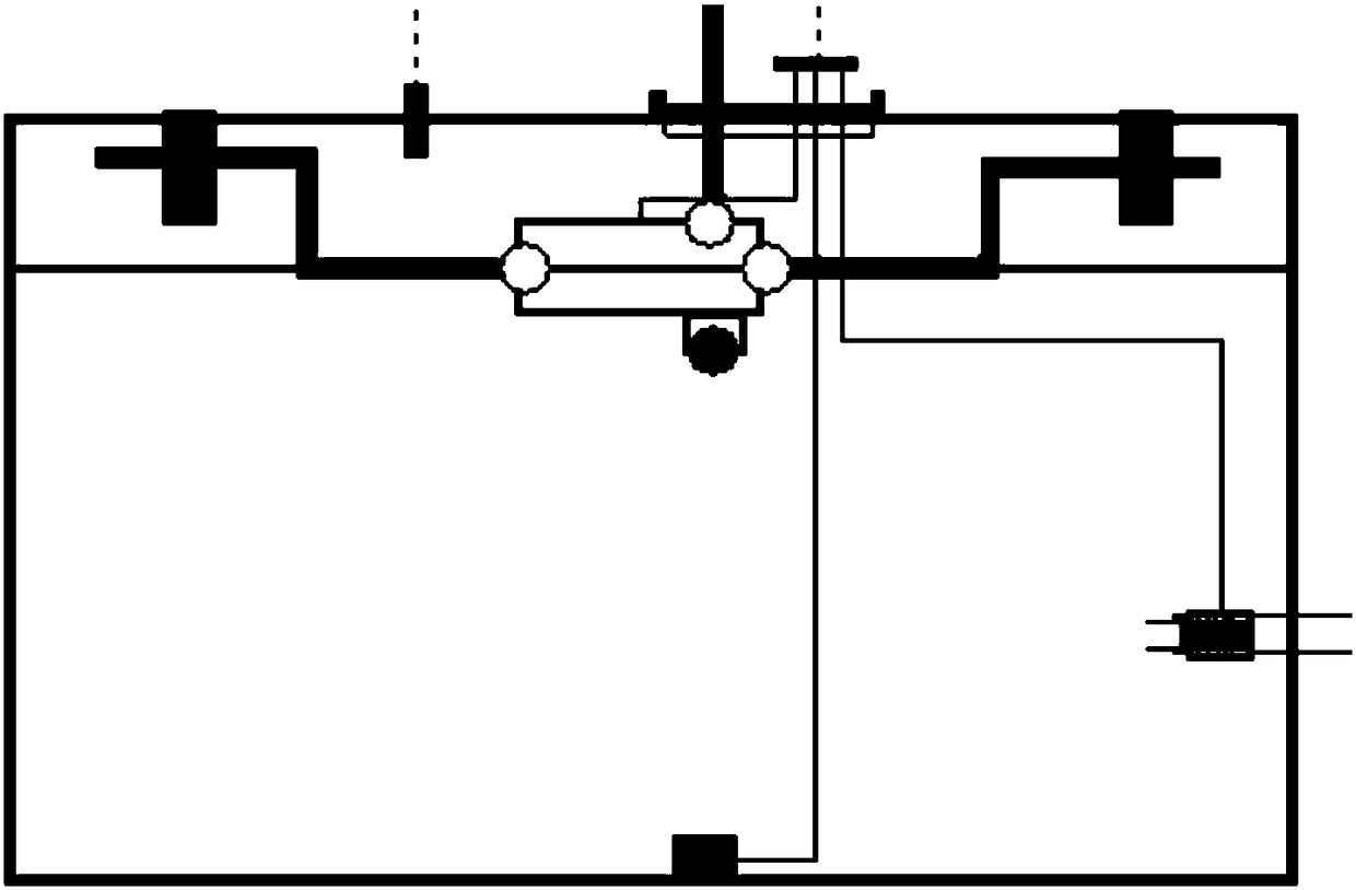
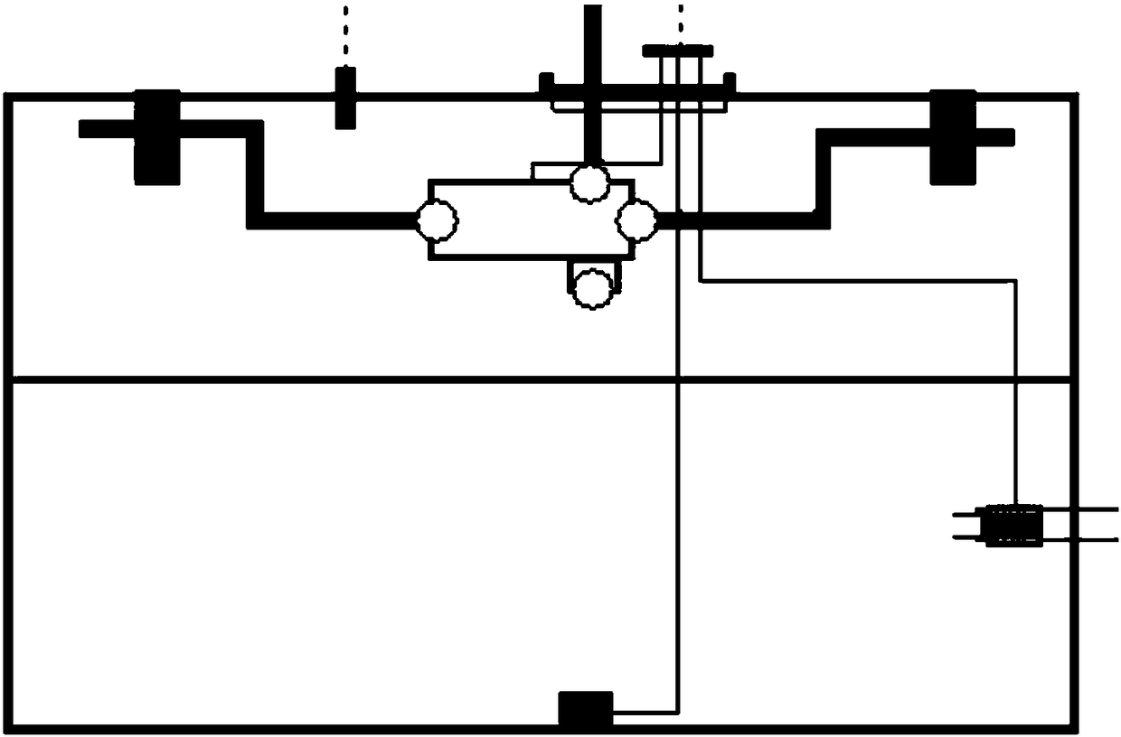
[0032] Example 2: see figure 1 , as an improvement of the present invention, the electronically controlled exhaust valve 5 adopts a combined structure of an electromagnetic valve and a mechanical valve, so that it has two valve flow directions of exhaust and liquid discharge, and the electromagnetic valve module and the mechanical valve The valve modules all have a two-stage opening mode. The electromagnetic valve is in the mode of large flow and small flow to control the ventilation volume; the closed state of the mechanical valve module is to close the valve and the drain port of the fuel tank and the interface between the valve and the air port leading to the carbon tank at the same time, and the first-level open state is closed The valve and the drain port of the fuel tank prevent fuel from entering the carbon tank through the valve, and open the interface between the valve and the vent leading to the carbon tank. The vent interface, such as Figure 2a , 2b shown. This...

Embodiment 3

[0033] Embodiment 3: As an improvement of the present invention, the liquid level sensor 8 adopts a piezoresistive pressure sensor as a measuring device, and uses a strain gauge (DMS) method for pressure measurement. Silicon wafer is selected as DMS, and metal (steel) is used as thin film. The signal generated by the pressure sensor is sent to the electronic control unit after temperature compensation. Combined with the internal air pressure signal measured by the air pressure sensor, the accurate fuel level information is obtained through algorithm analysis. . Different types of fuel tanks only need to determine the installation position of the sensor, and use the algorithm to calibrate the liquid level, instead of redesigning the valve according to the fuel tank structure and closing height like the traditional fuel system. The rest of the structures and advantages are exactly the same as in Embodiment 1.


PUM


Abstract

The invention relates to a novel electric control fuel oil system. The novel electric control fuel oil system comprises a fuel tank body, a carbon tank, an oil filling pipe, an oil pump, an electric control exhaust valve, air vents, an air pressure sensor, a liquid level sensor, an air vent pipe, an oil supply/return pipeline, a control unit and an electric control check valve. The air vents of the carbon tank and a fuel tank are in communication with the electric control exhaust valve through the air vent pipe, the electric control exhaust valve is arranged in the fuel tank body, and a pressure type liquid level sensor is arranged at the bottom of the fuel tank body. The air pressure sensor is arranged at the top of the fuel tank body, the electric control check valve is arranged at the joint of the oil filling pipe and the fuel tank body, and the control unit communicates with the whole vehicle ECU in the form of a CAN bus. According to the technical scheme, the design is ingenious,and the structure is compact. The rapidity and high sensitivity of an electric control valve are utilized to quickly exhaust gas to control the internal pressure, the smoothness of oil filling is improved, and the phenomena of back injection and back surge are eliminated.

Description

technical field [0001] The invention relates to a fuel system, in particular to a novel electronically controlled fuel system, which belongs to the technical field of fuel tank structural components. Background technique [0002] The fuel system is a part of the automobile chassis or powertrain system. Its main function is to provide fuel for the automobile engine. The fuel system can be divided into four modules according to the function, namely the fuel storage module, the fuel transmission module, the steam management module, and the measurement control module. module. [0003] During the refueling process of the car, the vapor in the fuel tank is required to be discharged to the carbon tank through the pipeline for desorption treatment. When refueling reaches the automatic jump gun, the fuel volume in the fuel tank meets the requirements. The current fuel system uses the "liquid level control valve" to close and cut off the exhaust at a certain height, so that the fuel ...

Claims


Application Information

Patent Timeline
IPC IPC(8): B60K15/03B60K15/035
CPCB60K15/03B60K15/035B60K2015/03571B60K2015/03576B60K2015/03585B60K2015/03566B60K2015/03388B60K2015/03302B60K2015/03217B60K2015/0321B60K2015/0319
Inventor 姜林刘亮翁益明孙超韩典臣
Owner YAPP AUTOMOTIVE PARTS
Why Eureka
Try Eureka