Double-rotor hybrid excitation permanent magnet synchronous motor for electric vehicle and method thereof

A hybrid excitation, permanent magnet synchronous technology, applied in electric vehicles, synchronous machines, synchronous machine parts, etc., can solve problems such as narrow constant power operating range, large armature back EMF harmonics, and increased motor leakage flux. , to achieve the effect of good structure compactness and high effective magnetic density of air gap

Pending Publication Date: 2018-08-17
SHANDONG UNIV
View PDF12 Cites 7 Cited by
  • Summary
  • Abstract
  • Description
  • Claims
  • Application Information

AI Technical Summary

Problems solved by technology

[0022] 1. The permanent magnet synchronous motor has a fixed permanent magnet magnetomotive force, and the main magnetic flux of the motor cannot be adjusted, resulting in a narrow constant power operating range and a wide range of speed regulation.
[0023] 2. In the existing built-in permanent magnet synchronous motor rotor structure, the permanent magnets of the rotor realize the "magnetism gathering effect" through various combinations, so the magnetic pole magnetic density of the rotor iron core is very high, so that there is a large leakage flux at its end , the rotor leakage flux is closed by the end of the motor rotor or the end cover. Since the total magnetic flux generated by the permanent magnet is constant, the existence of the end leakage flux not only makes the magnetic field distribution at the two ends of the motor uneven, but also reduces the Effective magnetic flux utilization, thereby reducing the power density and torque density of the motor. In order to overcome the influence of the end leakage flux, in actual design, the motor rotor often adopts an overhang structure, so that the axial length of the rotor core is greater than that of the motor stator. The axial length of the core, but this structure significantly increases the axial length of the motor, which in turn increases the amount of core material and manufacturing cost of the motor, and this structure does not essentially have the effect of suppressing the leakage flux at the end
[0025] 4. According to the different paths of the d-axis magnetic flux during field weakening, the existing permanent magnet synchronous motors with built-in rotor structure can be divided into two categories, one of which is the d-axis generated by the armature winding during field-weakening control. The magnetic flux will pass through the permanent magnet of the motor, causing irreversible demagnetization of the permanent magnet. In the other category, when the field weakening control is performed, the d-axis magnetic flux generated by the armature winding does not pass through the permanent magnet, but the magnetic field generated by the d-axis current Forcing more rotor flux through the ends of the motor and closing the end caps significantly increases the leakage flux of the motor, and since the end reluctance of the motor is usually much larger than the air gap reluctance, field weakening The required d-axis current is relatively large, which significantly increases the cost of the motor power inverter and the copper loss of the winding,
[0026] 5. The existing permanent magnet synchronous motors usually have large armature back electromotive force harmonics, and the problem of cogging torque is prominent, which will cause serious vibration and noise problems. The commonly used improvement methods are stator chute or rotor oblique poles. method to improve the counter electromotive force harmonics and weaken the cogging torque, but the processing technology of the stator chute and the rotor slant pole is relatively complicated, which greatly increases the manufacturing cost, and will reduce the average electromagnetic torque of the motor to a certain extent, and reduce the The power density and torque density of

Method used


Image

  • Double-rotor hybrid excitation permanent magnet synchronous motor for electric vehicle and method thereof
  • Double-rotor hybrid excitation permanent magnet synchronous motor for electric vehicle and method thereof
  • Double-rotor hybrid excitation permanent magnet synchronous motor for electric vehicle and method thereof

Examples


specific Embodiment

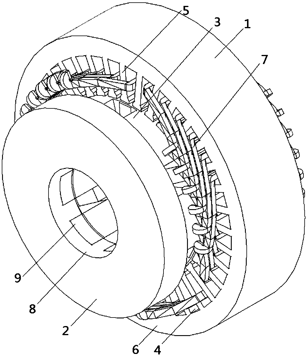
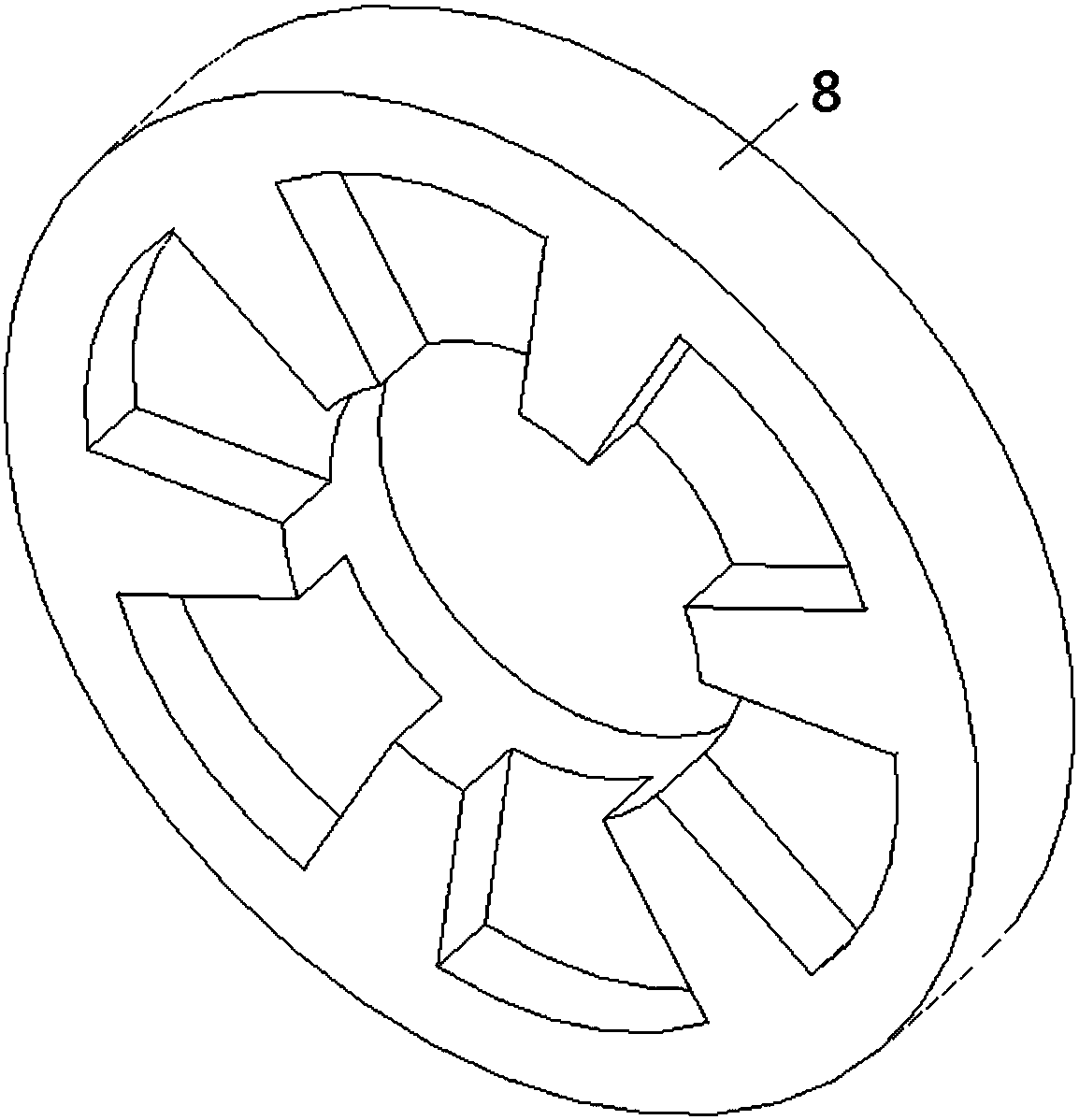
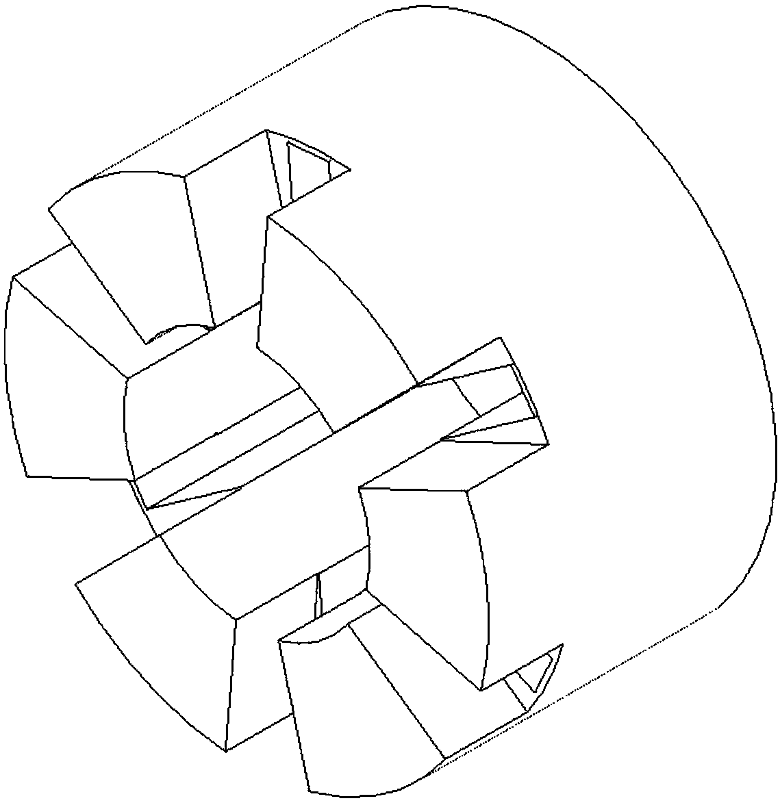
[0088] Such as figure 1Shown is a schematic diagram of the overall structure of the dual-rotor hybrid excitation permanent magnet synchronous motor for electric vehicles. The number of phases of the permanent magnet synchronous motor in this embodiment is 3, the number of radial stator teeth is 36, the number of radial rotor slots is 6, and the number of radial rotor slots is 6. The number of upper permanent magnet blocks is 6, the axial rotor has 6 permanent magnet placement slots, and the number of permanent magnet blocks on the axial rotor is 6. In this embodiment, the dual-rotor composite structure hybrid excitation permanent magnet synchronous motor for electric vehicles includes radial A stator 1, an axial rotor 2 and a radial rotor 3, the radial rotor 3 is placed inside the radial stator 1 and placed coaxially with the radial stator 1, and there is a gap between the radial rotor 3 and the radial stator 1 Radial air gap, the axial rotor 2 is installed at the end of the r...


PUM


Abstract

The invention discloses a double-rotor hybrid excitation permanent magnet synchronous motor for an electric vehicle and a method thereof. The motor comprises a radial stator, an axial rotor and a radial rotor. The radial rotor is placed inside the radial stator and is coaxially arranged with the radial stator. The radial rotor is provided with the axial rotor at the end portion, and the axial rotor is coaxially arranged with the radial rotor. The axial rotor is driven by a servo motor to rotate, so that the axial rotor and the radial rotor maintain the same rotational speed. The radial rotor is provided with a permanent magnet thereon. A part of the magnetic flux generated by the permanent magnet enters the radial stator through a radial gap to generate a radial main magnetic flux, and theother part enters the axial rotor through an axial air gap to generate an axial main magnetic flux. The axial magnetic flux and the radial magnetic flux are in a parallel relationship. The axial magnetic flux of the radial rotor can be adjusted by changing the relative positions of the axial rotor and the radial rotor. Therefore, the radial magnetic flux of the radial rotor is indirectly controlled, the hybrid excitation function is achieved and the economic operating range of the electric vehicle drive motor is expanded.

Description

technical field [0001] The invention relates to a permanent magnet synchronous motor, in particular to a double rotor composite structure hybrid excitation permanent magnet synchronous motor for an electric vehicle and a method thereof. Background technique [0002] In recent years, with the improvement of high temperature resistance and price reduction of permanent magnet materials, permanent magnet motors have been widely used in national defense, industry, agriculture and daily life, and are moving towards high power, high functionality and miniaturization. With the development, the varieties and application fields of permanent magnet motors continue to expand. At present, the power of permanent magnet motors ranges from a few milliwatts to thousands of kilowatts, and the application scope ranges from small toy motors to large permanent magnet motors used in ship traction. They are used in various aspects of the national economy, daily life, military industry, and aerospa...

Claims


Application Information

Patent Timeline
Patent Type & Authority Applications(China)
IPC IPC(8): H02K16/02H02K21/04H02K1/27
CPCH02K1/2766H02K16/02H02K21/042H02K2201/03Y02T10/64
Inventor 王道涵王秀和
Owner SHANDONG UNIV
Why Eureka
Try Eureka