Laser shock technology for improving ion nitriding efficiency

A technology of laser shock and ion nitriding, applied in metal material coating process, coating, solid-state diffusion coating, etc., can solve the problems of low ion nitriding speed, surface lattice distortion, high residual compressive stress, etc. To achieve the effect of increasing the thickness of the infiltrated layer, increasing the infiltrated concentration, and improving the uneven structure of the infiltrated layer

Inactive Publication Date: 2018-08-24
CHANGZHOU UNIV
View PDF6 Cites 8 Cited by
  • Summary
  • Abstract
  • Description
  • Claims
  • Application Information

AI Technical Summary

Problems solved by technology

[0005] The technical problem to be solved by the present invention is: based on the above-mentioned problems of low ion nitriding speed and long process cycle, the present invention provides a laser shock process for improving the efficiency of ion nitriding, and obtai

Method used


Image

  • Laser shock technology for improving ion nitriding efficiency
  • Laser shock technology for improving ion nitriding efficiency
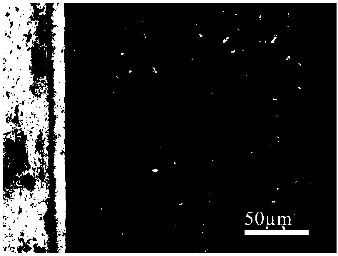
  • Laser shock technology for improving ion nitriding efficiency

Examples


Embodiment 1

[0024] (1) Process the raw steel into a sample with a size of 10mm×10mm×5mm;

[0025] (2) Refining and tempering the sample, first raising the temperature to 860°C for 12 minutes, then oil cooling, then raising the temperature to 600°C for 30 minutes, then air cooling to room temperature;

[0026] (3) Grind the sample with 500#~2000# SiC sandpaper to the mirror surface, wash with deionized water and soak in 20ml of acetone, perform ultrasonic cleaning for 15min to remove oil, and dry it for use;

[0027] (4) Clamp the sample on the laser shock strengthening test platform, set the laser wavelength to 1064nm, the pulse width to 10ns, the laser energy to 3J, the shape of the spot to be circular, the diameter of the spot to be 3mm, and the overlapping rate of the spot to be 50%; the laser passes through the transparent flowing water The layer acts on the black tape coating coated on the surface of the sample. The black tape coating absorbs the laser energy and induces high-intensi...

Embodiment 2

[0031] (1) Process the raw steel into a sample with a size of 10mm×10mm×5mm;

[0032] (2) Refining and tempering the sample, first raising the temperature to 860°C for 12 minutes, then oil cooling, then raising the temperature to 600°C for 30 minutes, then air cooling to room temperature;

[0033] (3) Grind the sample with 500#~2000# SiC sandpaper to the mirror surface, wash with deionized water and soak in 20ml of acetone, perform ultrasonic cleaning for 15min to remove oil, and dry it for use;

[0034] (4) Clamp the sample on the laser shock strengthening test platform, set the laser wavelength to 1064nm, the pulse width to 30ns, the laser energy to 10J, the shape of the spot to be circular, the diameter of the spot to be 3mm, and the overlapping rate of the spot to be 50%; the laser passes through the transparent flowing water The layer acts on the black tape coating coated on the surface of the sample. The black tape coating absorbs the laser energy and induces high-intens...


PUM

PropertyMeasurementUnit
Thicknessaaaaaaaaaa

Abstract

The invention relates to a laser shock technology for improving the ion nitriding efficiency. The technology comprises the following steps: processing and cutting raw steel to form a sample; quenchingand tempering the sample, polishing the sample, ultrasonically cleaning the polished sample in an organic solvent, and drying the cleaned sample; clamping the sample to a laser shock peening test platform, and performing laser shock treatment on the surface; and placing the sample in an ion nitriding furnace, performing ion nitriding treatment, and performing furnace cooling to room temperature.The technology has the following advantages: laser shock treatment causes plastic deformation of the surface layer of a material to form high density dislocations, refine crystal grains and even generate nanocrystals, so diffusion channels are provided for nitrogen atom diffusion, and the diffusion activation energy is reduced, thereby the technology significantly increases the nitriding efficiency, and has the advantages of high efficiency and energy saving.

Description

technical field [0001] The invention relates to a laser shock process for improving ion nitriding efficiency. Background technique [0002] In engineering applications, ion nitriding is a widely used surface heat treatment technology. Active nitrogen atoms are generated through the phenomenon of gas glow discharge, enriched on the surface of the workpiece and continuously diffused into the matrix to form a nitrided layer. Ion nitriding can significantly improve the wear resistance and service life of metal parts. It has many advantages such as low nitriding temperature, uniform nitriding layer, and environmental protection. However, low infiltration speed and long process cycle are problems that restrict the development of this technology. Explore and improve the nitriding process to increase the efficiency of ion nitriding. [0003] In recent years, the technology of combined shot peening (sand blasting) and ion nitriding has been developed rapidly. After the workpiece is...

Claims


Application Information

Patent Timeline
IPC IPC(8): C21D10/00C23C8/02C23C8/38
CPCC21D10/005C23C8/02C23C8/38
Inventor 胡静唐磊贾蔚菊
Owner CHANGZHOU UNIV
Why Eureka
Try Eureka