Internal cylinder body and rotary internal combustion engine

A technology for internal cylinders and internal combustion engines, applied to internal combustion piston engines, combustion engines, mechanical equipment, etc., can solve the problems of mechanical inertia conversion loss, affecting air intake efficiency, and low mechanical efficiency, so as to improve efficiency and economy. Improve the effect of complex structure and low manufacturing cost

Pending Publication Date: 2018-09-07
陈东生
View PDF2 Cites 0 Cited by
  • Summary
  • Abstract
  • Description
  • Claims
  • Application Information

AI Technical Summary

Problems solved by technology

According to the four working processes, it can be concluded that the reciprocating piston internal combustion engine has the following disadvantages, the loss of ventilation, the delayed closing of the exhaust valve and the early opening of the intake valve have an overlapping period, the encounter between the residual gas and the fresh air entering the cylinder cannot be precisely controlled, there will be The fresh air is discharged along with the residual gas, and the residual gas with a higher temperature will stay in the combustion chamber, and the intake temperature will increase, which will affect the intake efficiency; the conversion loss of mechanical motion inertia, the piston is converted from linear motion to circular motion through the crank connecting rod , four strokes have four dead centers, due to the large loss of mass motion inertia of the piston and connecting rod itself; thermal friction loss, when the piston starts to work, the piston is at the top dead center, and the piston, connecting rod, and crank are on the same straight line. There is a period of residence time. At this moment, the high-temperature and high-pressure gas cannot be released quickly. The extremely high pressure is applied to the piston and crank connecting rod, which makes the lubricating oil film of each bearing bearing thinner and increases the contact friction. The working gas has elastic properties. When it cannot be released quickly , part of the energy is transferred to the body in the form of heat energy, and heat radiation is increased; the power loss caused by the auxiliary mechanism, the intake and exhaust need to be realized by the camshaft and the valve group mechanism, and the intake and exhaust valves are driven by the camshaft. The camshaft timing chain is driven by the crankshaft, and the cam needs to overcome the valve spring to drive the valve to open and close. The entire gas distribution system does not participate in the work, but consumes 5-8% of the power, and the mechanism becomes complicated; the mechanical efficiency is low. Only one of the strokes does work, and the non-work stroke consumes part of the power; the output torque is uneven and intermittent. When the power output does not match the load, the output torque will falter, which requires a larger flywheel. Intermittent point; poor stability, due to the crankshaft connecting rod mechanism, the force changes in all directions during motion are more complicated, the stability of the whole machine is poor, and a balance shaft needs to be added to improve the stability of the engine; the fuel combustion utilization rate is low, In the power stroke, the exhaust valve needs to be opened 30°~80° in advance before the power is finished, so that the high-pressure combustion gas cannot be effectively used and discharged out of the cylinder. In addition, the volume of the intake air is equal to the volume of the power. The volume of the high-temperature and high-pressure gas generated is more than 6 times the volume of the intake air, and the part of the combustion gas outside the same volume still has a relatively high pressure, and there is still a high value of power acquisition, especially in the initial stage after the exhaust valve is opened; The working temperature of the combustion chamber is limited, which affects the combustion efficiency. The working temperature of the traditional engine combustion chamber cannot be operated at a high temperature. When the temperature of the combustion chamber exceeds the rated temperature, there will be deflagration. Deflagration often occurs when the piston has not reached the upper stop. Generated before the point, the combustion speed of the mixture propagates at the speed of sound, and the extreme high temperature and high pressure gas is applied to the piston connecting rod, causing destructive damage to the engine

Method used


Image

  • Internal cylinder body and rotary internal combustion engine
  • Internal cylinder body and rotary internal combustion engine
  • Internal cylinder body and rotary internal combustion engine

Examples


Embodiment 1

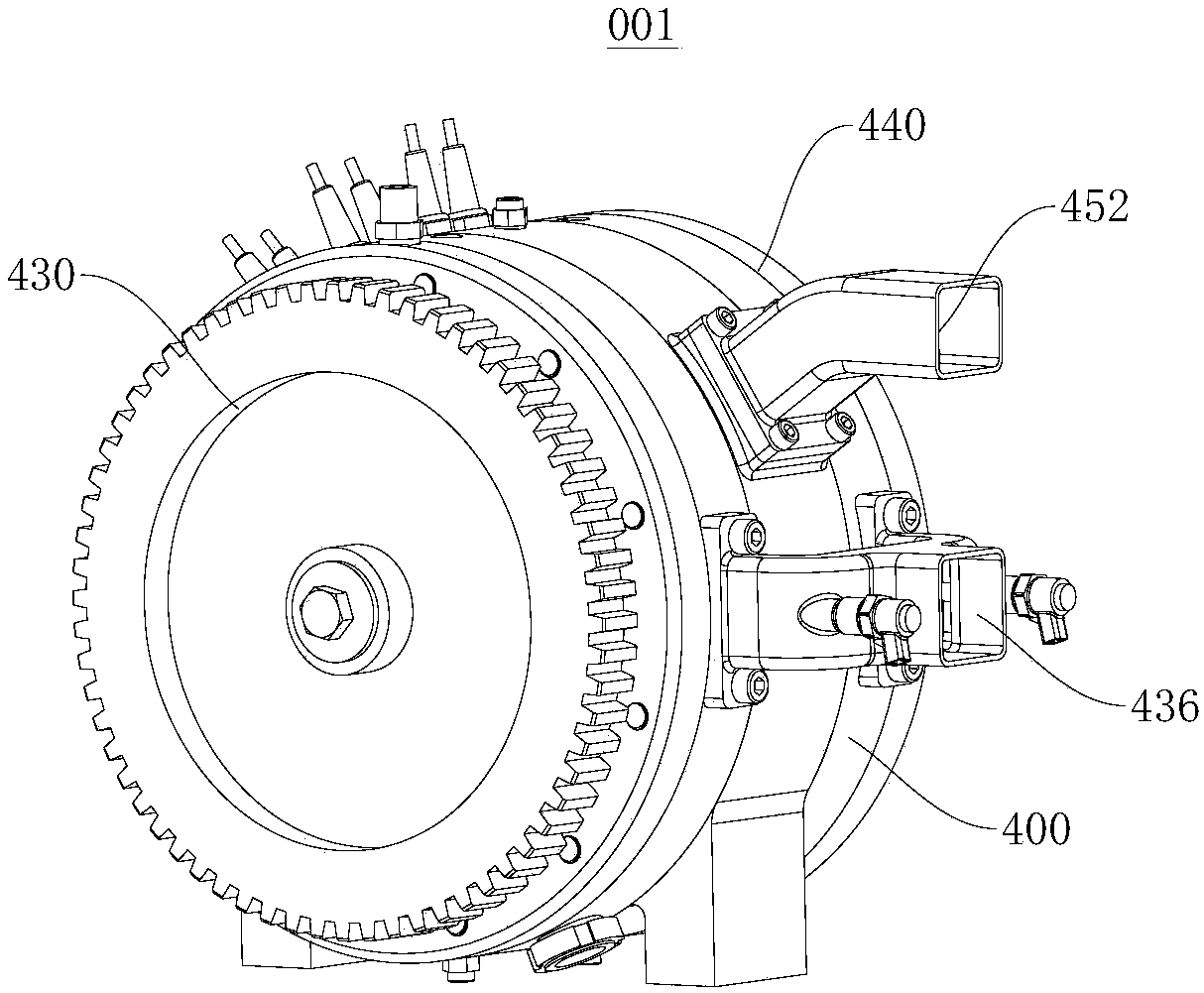
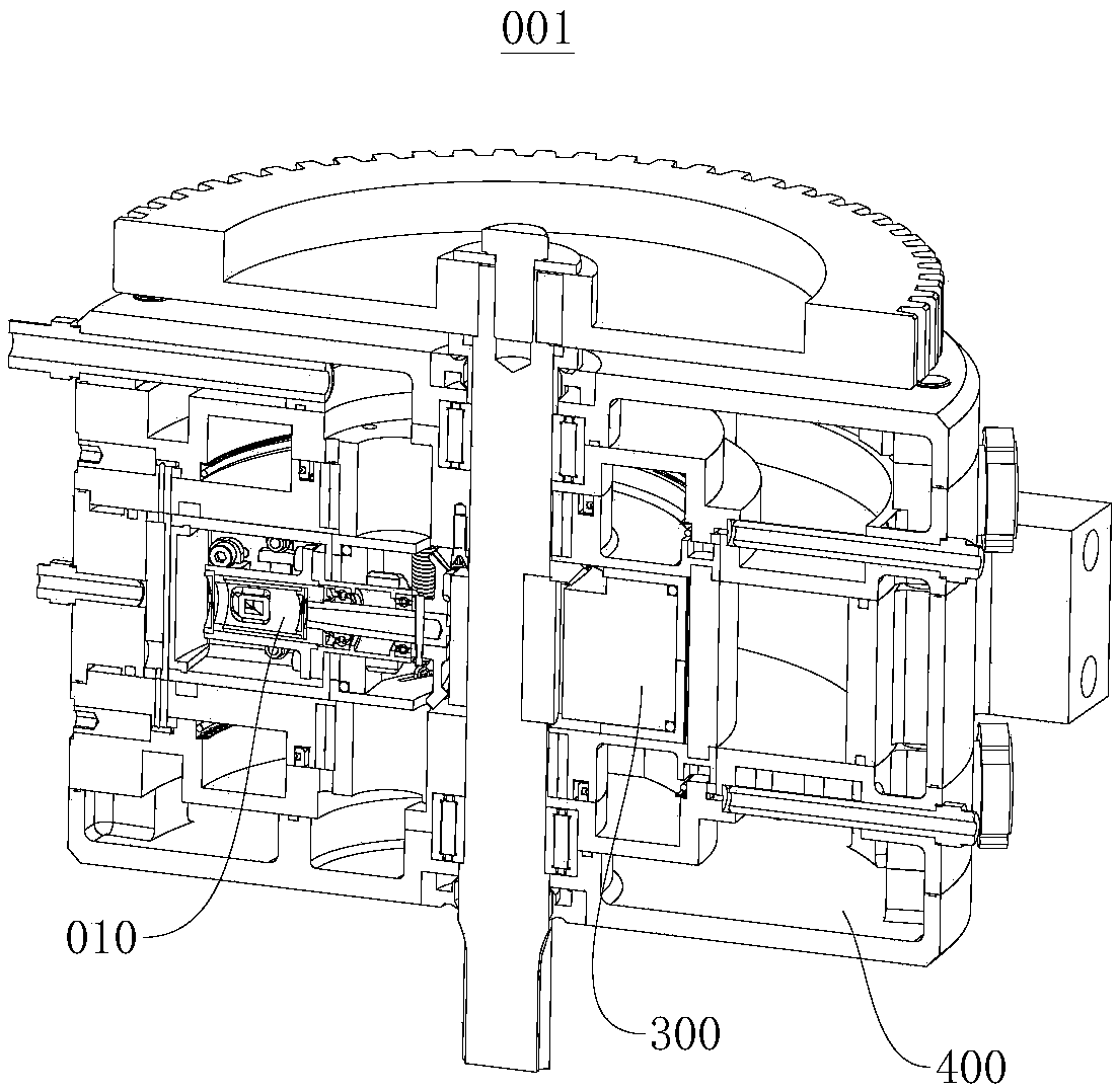
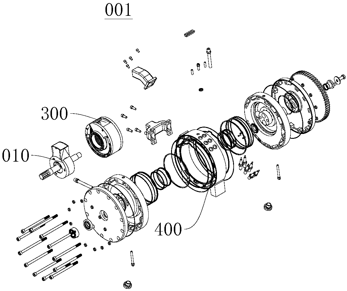
[0049] refer to Figure 1 to Figure 15 , the present invention provides a rotary internal combustion engine 001, comprising an outer cylinder 400, an inner cylinder 300 and a piston shaft assembly 010, an exhaust passage 452, an intake passage 434 and a spark plug 410 are arranged on the peripheral wall of the outer cylinder 400, The inner cylinder 300 is rotatably connected to the outer cylinder 400, the inner cylinder 300 rotates around its axis relative to the outer cylinder 400, and the axis of the inner cylinder 300 is staggered from the axis of the outer cylinder 400, The outer wall of the inner cylinder 300 is cut from the inner wall of the outer cylinder 400; the piston shaft assembly 010 includes a piston assembly 200 and a screw frame, the piston assembly 200 is installed on the screw frame, the screw frame is located in the inner cylinder 300, and the screw The frame is rotatably connected with the outer cylinder body 400, the spiral frame rotates relative to the ou...

Embodiment 2

[0073] Please refer to the drawings in Embodiment 1, the present invention also provides a rotary internal combustion engine 001, comprising an outer cylinder 400, an inner cylinder 300 and a piston shaft assembly 010, and an exhaust passage is arranged on the peripheral wall of the outer cylinder 400 , air inlet and spark plug, the inner cylinder 300 is connected to the outer cylinder 400 in rotation, the inner cylinder 300 rotates around its axis relative to the outer cylinder 400, and the axis of the inner cylinder 300 is connected to the outer cylinder 400 The axis line of the cylinder is staggered, and the outer wall of the inner cylinder 300 is cut to the inner wall of the outer cylinder 400; the piston shaft assembly 010 includes a screw frame and more than two piston assemblies 200, and more than two piston assemblies 200 They are respectively installed on the spiral frame, and more than two piston assemblies 200 are arranged at equal intervals around the axis line of t...


PUM


Abstract

The invention provides an internal cylinder body and a rotary internal combustion engine and belongs to the field of internal combustion engines. The internal cylinder body comprises a C-shaped internal cylinder sleeve, a sealing elastic piece and two end covers. The internal combustion engine comprises an external cylinder body, the internal cylinder body and a piston shaft assembly. The circumferential wall of the external cylinder body is provided with an air outlet, an air inlet and a sparking plug. The internal cylinder body is rotationally connected with the external cylinder body. The internal cylinder body rotates, relative to the external cylinder body, around the axis of the internal cylinder body, the axis of the internal cylinder body and the axis of the external cylinder bodyare arranged in a stagger manner, and the side wall of the internal cylinder body and the side wall of the external cylinder body are tangent to each other. The piston shaft assembly comprises pistonassemblies and a spiral frame, wherein the piston assemblies are installed on the spiral frame, the spiral frame is located in the internal cylinder body, the spiral frame is rotationally connected with the external cylinder body, and the spiral frame rotates, relative to the external cylinder body, around the axis of the spiral frame. The internal cylinder body and the rotary internal combustionengine have the beneficial effects of being small in size, small in weight, good in stability, low in manufacturing cost and oil consumption and the like.

Description

technical field [0001] The invention relates to the field of internal combustion engines, in particular to an inner cylinder block and a rotary internal combustion engine. Background technique [0002] The reciprocating piston internal combustion engine (oil, gas ignition engine) is an engine that converts the heat energy generated by fuel combustion into mechanical energy. The ignition engine that is commonly used now still follows the Otto cycle, that is, intake, compression, work and exhaust. In the four strokes, the compressed mixed gas is discharged by the spark plug electrode, and the mixed gas is ignited for combustion. The volume change in the cylinder of the four strokes is realized by the piston movement driven by the crank connecting rod. According to the four working processes, it can be concluded that the reciprocating piston internal combustion engine has the following disadvantages, the loss of ventilation, the delayed closing of the exhaust valve and the earl...

Claims


Application Information

Patent Timeline
Patent Type & Authority Applications(China)
IPC IPC(8): F02B55/08F02B55/16F02B55/02F02B53/00
CPCF02B53/00F02B55/02F02B55/08F02B55/16Y02T10/12
Inventor 陈东生史纪元
Owner 陈东生
Why Eureka
Try Eureka