
System and method for producing hydrogen fuel gas by low-energy nuclear reaction

A technology for fuel gas and hydrogen production, applied in the field of low-energy nuclear reactions, can solve problems such as increasing CO2 emissions, and achieve the effect of small safety scale

Inactive Publication Date: 2018-11-30
任海峰
View PDF4 Cites 0 Cited by
  • Summary
  • Abstract
  • Description
  • Claims
  • Application Information

AI Technical Summary

Problems solved by technology

However, at present, most hydrogen energy is obtained from coal, petroleum or biomass, or electrolyzed water to produce hydrogen, which still has not essentially eliminated carbon dioxide emissions, while electrolyzed water to produce hydrogen will increase CO2 emissions. Hydrogen production Hydrogen is used for power generation, and the heat utilization rate can only reach 4%

Method used


Image

  • System and method for producing hydrogen fuel gas by low-energy nuclear reaction

Examples


specific Embodiment 1

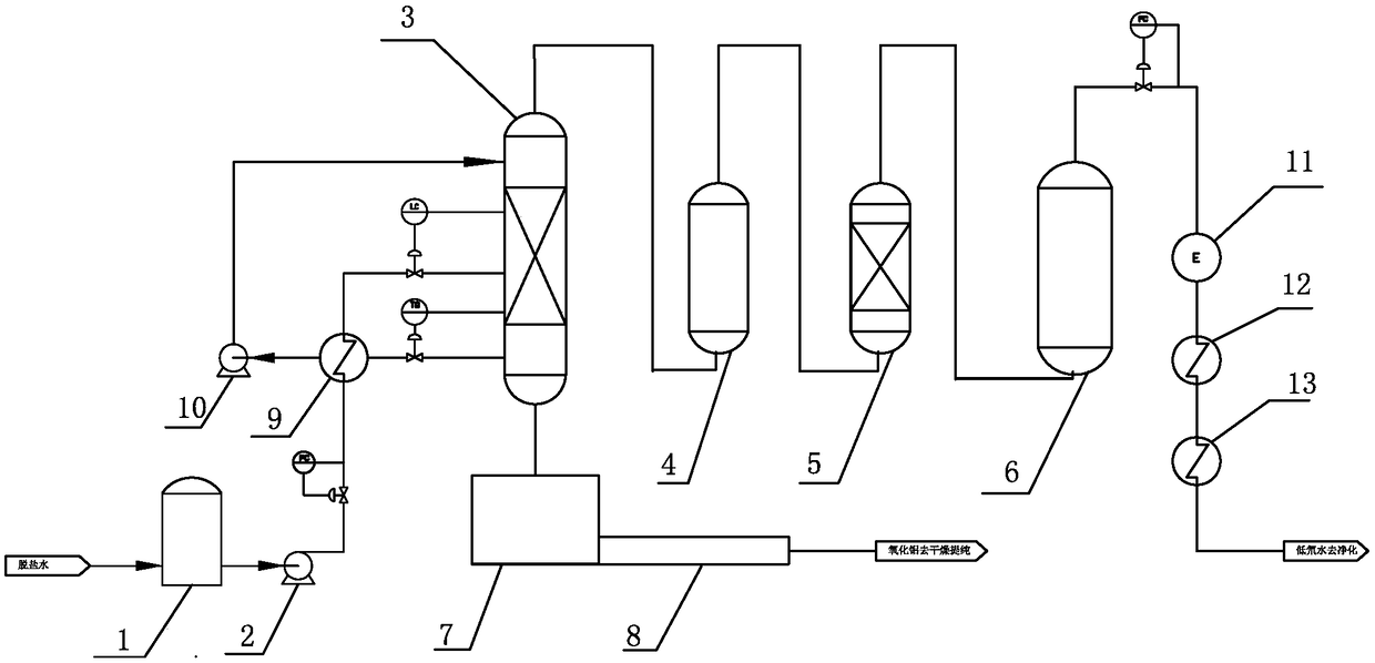
[0040] A low-energy nuclear reaction system to produce hydrogen fuel gas, such as figure 1 As shown, including desalinated water tank 1, reaction feed pump 2, low-energy nuclear reactor 3, buffer tank 4, filter 5, gas storage tank 6, precipitation tank 7, screw conveyor 8, water preheater 9, reaction circulation pump 10. Hydrogen internal combustion generator set 11, waste heat recovery heat exchanger 12 and deuterium-depleted water condenser 13, the desalinated water tank 1 is provided with a water inlet, and the bottom water outlet of the desalinated tank 1 is connected with the water inlet of the reaction feed pump 2, and the reaction inlet The water outlet of the feed pump 2 is connected with the cold water inlet of the water preheater 9, the hot water outlet of the water preheater 9 is connected with the middle water inlet of the low energy nuclear reactor 3, and the bottom water outlet of the low energy nuclear reactor 3 is connected with the water preheater The hot water...

specific Embodiment 2

[0042] A method for producing hydrogen fuel gas by low-energy nuclear reaction using the system of specific embodiment 2, such as figure 1 As shown, including the following steps:

[0043] (1) Feed the raw water (soft water, boiler deaerated water, distilled water and other clean water can be used as raw material water for production) into the desalinated water tank 1 for desalination, and then preheat the desalinated water to 85°C through the preheater. Enter the low-energy nuclear reactor 3;

[0044] (2) The metal catalyst aluminum is fed into the low-energy nuclear reactor 3 containing desalinated water at 85°C. After the metal catalyst aluminum is in contact with water for 5-30 minutes, there is no need for any external heat source or energy source. The metal catalyst aluminum reacts with water automatically to generate heat , The water temperature in the low-energy nuclear reactor 3 will gradually rise, and the pressure in the low-energy nuclear reactor 3 will gradually incre...


PUM


Abstract

The invention discloses a system and method for producing hydrogen fuel gas by low-energy nuclear reaction. The technical scheme is characterized in that the system comprises a desalting tank, a reaction feeding pump, a water preheater, a low-energy nuclear reactor, a buffer tank, a filter, a gas storage tank, a hydrogen internal combustion generator set, a waste heat-recovery heat exchanger and alow-deuterium water condenser, wherein a bottom by-product discharge port of the low-energy nuclear reactor is connected with a sedimentation tank, the sedimentation tank is connected with a screw conveyor, and a reaction circulation pump is disposed between a cold water outlet of the water preheater and a top circulating water inlet of the low-energy nuclear reactor; and the method includes a step of low-energy nuclear reaction, a step of hydrogen fuel gas purification, and a step of hydrogen storage and utilization. The technical scheme has the advantage that a huge amount of energy can begenerated without producing greenhouse gases or polluting the environment.

Description

Technical field [0001] The invention relates to a low-energy nuclear reaction, in particular to a low-energy nuclear reaction system and method for producing hydrogen fuel gas. Background technique [0002] my country has become the world’s largest energy producer and consumer, facing challenges such as in-depth adjustment of the world’s energy landscape, accelerated global action to respond to climate change, increasingly fierce technological competition among countries, the entry of a new normal in the domestic economy, and the continuous strengthening of resource and environmental constraints. It is urgent to build a clean, low-carbon, safe and efficient modern energy system. [0003] According to data released by the National Bureau of Statistics, my country's total energy consumption in 2016 was 4.67 billion tons of standard coal. Among them, the total coal consumption is 32, the total oil consumption is 7.4, the total natural gas consumption is 2.7, and the total consumption ...

Claims


Application Information

Patent Timeline
IPC IPC(8): C01B3/08C01F7/42C01B5/00G21B3/00
CPCC01B3/08C01B5/00C01F7/428G21B3/00Y02E30/10Y02E60/36Y02P20/10Y02P20/129
Inventor 任海峰姜国新
Owner 任海峰
Learn More