Electronic cutting device and metal fusing agent grain

A charge and fusing technology, applied in metal processing equipment, explosives, welding equipment, etc., can solve the problems that cutting tools cannot be carried quickly and work effectively, and are not applicable, and achieve a simple structure, low production cost, and easy to carry Effect

Pending Publication Date: 2018-12-18
NANJING FORESTRY UNIV
View PDF2 Cites 4 Cited by
  • Summary
  • Abstract
  • Description
  • Claims
  • Application Information

AI Technical Summary

Problems solved by technology

[0003] The usual thermal cutting methods include flame cutting, plasma cutting, CNC plasma cutting, etc. However, these cutting methods often require a power supply of more than one kilowatt and a heavy electric welding machine
These traditional cutting methods will become inapplicable if the power supply and electric welding machine cannot be effectively provided in the event of a power outage or in special environments such as the field, snowstorm or underwater
[0004] And for operations in an emergency environment or in a small space, the current cutting tools cannot be carried quickly and effectively

Method used


Image

  • Electronic cutting device and metal fusing agent grain

Examples


Embodiment 1

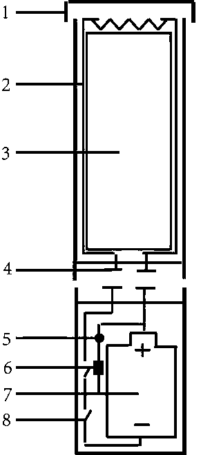
[0034] An electronic cutting device consists of an open casing 1 and a matching waterproof plug.

[0035] The shell 1 is divided into a control cavity and a grain cavity, and the grain cavity is placed at the open end of the shell 1; the grain cavity is used to accommodate the metal fusing reagent grain; the control cavity has a built-in drive circuit, including a metal wire 2 A battery 7, an indicator light 5, a resistor 6, a switch 8 arranged on the wall of the control cavity, and a heating resistor 6 wire arranged at the mouth of the grain column are connected in series.

[0036] The outer wall of the control cavity is provided with a handle, which is preferably made of insulating and non-slip material.

Embodiment 2

[0038] Based on an electronic cutting device in Example 1, the housing 1 is composed of a separable grain cavity and a control cavity; the control cavity is sealed, and the ends of the grain cavity and the control cavity are respectively provided with metal contact pieces 4, and the The metal contact piece 4 is connected to the driving circuit.

Embodiment 3

[0040] A metal fuse powder column 3 is composed of the following components by mass percentage: 60-70% of an oxidant, 15-25% of a reducing agent, 4-8% of an ignition agent, and 4-8% of a gas generator.

[0041] Among them, the oxidant is composed of ferric oxide, ferric tetroxide, copper oxide, cuprous oxide, manganese dioxide, manganese oxide, silicon dioxide, chromium oxide, boron oxide, beryllium oxide at least one constituent of lead;

[0042] The reducing agent is composed of at least one of aluminum powder, zinc powder, nickel powder, silicon powder and titanium powder;

[0043] The ignition agent is magnesium powder;

[0044] The gas generating agent is composed of at least one of potassium perchlorate, potassium chlorate, potassium nitrate and barium nitrate.

[0045] The preferred component 1 includes: ferric oxide 46%, copper oxide 23%; aluminum powder 20%; magnesium powder 4.5%; potassium perchlorate 6.5%.

[0046] And, 20% of the aluminum powder is composed of 1...


PUM

PropertyMeasurementUnit
diameteraaaaaaaaaa

Abstract

The invention discloses an electronic cutting device, which comprises a cavity casing provided with a plug in at an opening end, wherein the cavity is separated divided into a control cavity and a grain cavity; the grain cavity is arranged at the opening end; a metal fusing reagent grain is built in the grain cavity; a resistance wire is arranged at a the cavity opening; a driving circuit is builtin the control cavity, and comprises a battery and a switch; the battery is connected in series with the resistant wire; the switch is embedded in the wall of the control cavity wall; the metal fusing agent grain consists of the following materials in percentage by mass: 60 to 70 percent of oxidizing agents, 15 to 25 percent of reducing agents, 4 to 8 percent of igniting agents and 4 to 8 percentof gas generating forming agents in percentage by mass. The heat is provided through igniting the igniting agents by the resistance wire; oxidizing agents and reduction reducing agents react to generate fusion metal which is sprayed out by gas obtained after the gas generating agents are heated; , so that the cutting effect is further achieved. The cutting device does not need additional power supplies and air sources, and can be used in special environments such as underwater environments and land environments; the carrying is convenient; the operation is simple; high practicability and wideapplicability are realized.

Description

technical field [0001] The invention relates to an electronic cutting device, in particular to an electronic cutting device and a metal fuse powder column. Background technique [0002] Cutting operation is a necessary means to remove metal obstacles in special occasions such as emergency rescue and demolition. [0003] Common thermal cutting methods include flame cutting, plasma cutting, CNC plasma cutting, etc. However, these cutting methods often require the help of power sources above kW and heavy electric welding machines. These traditional cutting methods will become unsuitable if the power supply and welding machine cannot be effectively provided in the event of a power outage, or in special environments such as the wild, snowstorm or underwater. [0004] Moreover, for operations in emergency environments or in small spaces, the current cutting tools cannot be carried quickly and operated effectively. [0005] Therefore, it is necessary to develop a small, inexpensi...

Claims


Application Information

Patent Timeline
Patent Type & Authority Applications(China)
IPC IPC(8): C06B33/14B23K28/00
CPCC06B33/14B23K28/00
Inventor 王毓彤贾翀崔举庆张海洋韩书广
Owner NANJING FORESTRY UNIV
Why Eureka
Try Eureka