Method for preparing graphene sensor on composite material surface

A composite material and graphene technology, applied in the field of sensors, can solve the problems of lack of graphene sensors, many preparation steps, high cost, etc., and achieve the effect of low cost, simple preparation method and few steps

Active Publication Date: 2018-12-25
BEIHANG UNIV
View PDF5 Cites 12 Cited by
  • Summary
  • Abstract
  • Description
  • Claims
  • Application Information

AI Technical Summary

Problems solved by technology

However, reduced graphene oxide / graphite (GO) always chooses methods such as pyrolytic exfoliation, epitaxial growth, and chemical vapor deposition (CVD) to realize the fabrication of graphene sensors, which have many steps, large scale, and high cost. Research on graphene sensors for in situ structural health monitoring (SHM) of biocomposites is still missing

Method used


Image

  • Method for preparing graphene sensor on composite material surface
  • Method for preparing graphene sensor on composite material surface
  • Method for preparing graphene sensor on composite material surface

Examples


Embodiment 1

[0067] (1) The raw material is glass fiber / epoxy resin prepreg, which is prepared into a flat composite material board at 140°C by vacuum bagging process, with a thickness of 5mm and an area of ​​200mm×200mm.

[0068] (2) Disperse 300 mg of graphene oxide in 100 ml of deionized aqueous solution, and use an ultrasonic processor to disperse for 1 hour at a power of 480 W to obtain a uniform dispersion of graphene oxide. Using the X-Y-Z three-axis platform controlled by the motor, the composite material plate is kept heated at 100°C and assembled on the platform to ensure that the water in the solution can evaporate immediately when the graphene oxide dispersion is sprayed on the composite material. Put the graphene oxide solution in the airbrush and assemble the airbrush on the platform, adjust the air pressure of the airbrush to 5PSI, and prepare a graphene oxide film on the composite material plate with a thickness of 5 μm.

[0069] (3) Use a diode laser with a wavelength of 7...

Embodiment 2

[0076] Other steps are the same as in Example 1, the only difference is that the laser irradiation focusing multiples in step (3) are 5 times focusing and 50 times focusing respectively, and the scanning times are 50 times and 20 times respectively.

[0077] Test the resistance change of the graphene sensor element under different laser irradiation focusing multiples, the obtained results are as follows Figure 5 as shown, Figure 5 is the sheet resistance data of the graphene sensor element under laser 5x focus and 50x focus; according to Figure 5 It can be seen that as the number of laser irradiation increases, the sheet resistance becomes smaller and smaller, indicating that the reduction degree of graphene oxide is getting higher and higher, and the conductivity is getting better and better.

Embodiment 3

[0079] Measuring the resistance change of graphene sensors when the composite material undergoes tensile deformation

[0080] (1) The other steps are the same as in Example 1, except that the number of scanning times of laser irradiation in step (3) is 6.

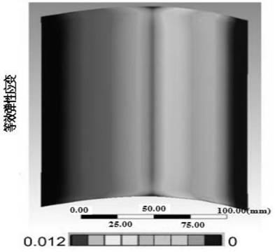
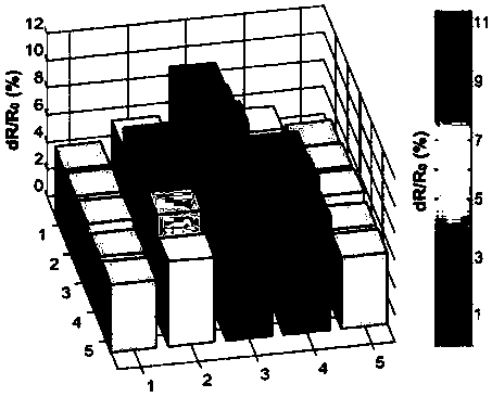
[0081] Make the composite material undergo different degrees of cyclic tensile deformation (0.2%, 0.4% and 0.6%), and detect the relative change of the resistance of the graphene sensor. The obtained results are as follows Figure 6 shown, according to Figure 6 It can be seen that the relative change in resistance of the graphene sensor is in good agreement with the tensile deformation during each test cycle, and the greater the mechanical strain, the greater the change in resistance.

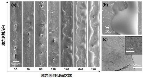
[0082] (2) The other steps are the same as in Example 1, except that the number of laser irradiation scans in step (3) is 4 times, 6 times, 8 times, 10 times and 40 times respectively.

[0083] The maximum strain level of the composite ma...


PUM

PropertyMeasurementUnit
concentrationaaaaaaaaaa
thicknessaaaaaaaaaa
wavelengthaaaaaaaaaa

Abstract

The invention provides a method for preparing a graphene sensor on the composite material surface. The method includes the steps that first, graphene oxide dispersion solution is atomized and deposited on the composite material surface to form a graphene oxide film; then the graphene oxide film is subjected to laser irradiation direct writing according to the predetermined sensor shape to form a graphene sensor element; and finally, a conductive silver paste electrode is printed to obtain the graphene sensor. According to the method for preparing the graphene sensor on the composite material surface, the graphene sensor can be directly prepared on composite materials with arbitrary surface, the preparation method is simple, the cost is low, and the shape, number and position of the graphene sensor elements can be adjusted; moreover, GF of the graphene sensor can be controlled by laser irradiation parameters, and the purpose of in-situ structural health monitoring of the composite materials using the graphene sensor is achieved; and the processing elements such as spraying of the graphene oxide dispersion solution, laser irradiation direct writing, and printing of the silver paste electrode are all completed by a three-axis platform program in a process controlled mode, and automatic production of the graphene sensor can be realized.

Description

technical field [0001] The invention relates to the technical field of sensors, in particular to a method for preparing graphene sensors on the surface of composite materials. Background technique [0002] Composite materials are multi-phase systems blended and modified by various materials. They have the characteristics of light weight, high strength and corrosion resistance. They are widely used in the aerospace field. With the advancement of composite material design and manufacturing technology, composite materials It has been possible to gradually replace the components of some key structural parts. Composite materials will be damaged under long-term service, and the damage is often due to damage to the internal microstructure, and the damage to the microstructure has a long-term impact on the controllability and safety of composite materials. Real-time online monitoring of composite materials can prevent sudden failure of structural components and improve the reliabil...

Claims


Application Information

Patent Timeline
Patent Type & Authority Applications(China)
IPC IPC(8): G01B7/16C01B32/184
CPCC01B32/184G01B7/18
Inventor 罗斯达王勇
Owner BEIHANG UNIV
Why Eureka
Try Eureka