System for treating chloroaluminate ionic liquid spent catalyst and alkaline wastewater

A technology of ionic liquid and waste catalyst, which is applied in sludge treatment, sedimentation treatment, natural water treatment, etc., can solve the problems of poor oil quality, high operating cost, high salt load and organic load, and achieve long contact time and thorough The effect of hydrolysis

Active Publication Date: 2019-01-11
CHINA UNIV OF PETROLEUM (BEIJING)
View PDF11 Cites 0 Cited by
  • Summary
  • Abstract
  • Description
  • Claims
  • Application Information

AI Technical Summary

Problems solved by technology

The above-mentioned method and system can harmlessly treat the spent chloroaluminate-based ionic liquid catalyst to a certain extent and realize the recycling of metals and acid-soluble oil in the spent catalyst. There are still the following defects: 1) directly adding alkali in the digestion reactor to digest-neutralize the spent catalyst, the reaction process is very violent, and the stability and safety of the process and system are relatively poor; 2) acid soluble in the spent catalyst Oil easily causes carbonization in digestion-neutralization reaction process, and the rate of recovery of acid-soluble oil is lower than 70%, and the water content of the acid-soluble oil that reclaims obtains in addition is high (moisture rate is about 7%), and there is particulate carbon impurity ( The content of particulate carbon impurities is about 5%), and the quality of the oil product is poor; 3) the

Method used


Image

  • System for treating chloroaluminate ionic liquid spent catalyst and alkaline wastewater
  • System for treating chloroaluminate ionic liquid spent catalyst and alkaline wastewater
  • System for treating chloroaluminate ionic liquid spent catalyst and alkaline wastewater

Examples


Example Embodiment

[0097] In order to make the objectives, technical solutions, and advantages of the present invention clearer, the following will clearly and completely describe the technical solutions in the embodiments of the present invention in conjunction with the accompanying drawings and embodiments of the present invention. Obviously, the described embodiments are the present invention. Invented some embodiments, but not all embodiments. Based on the embodiments of the present invention, all other embodiments obtained by those of ordinary skill in the art without creative work shall fall within the protection scope of the present invention.
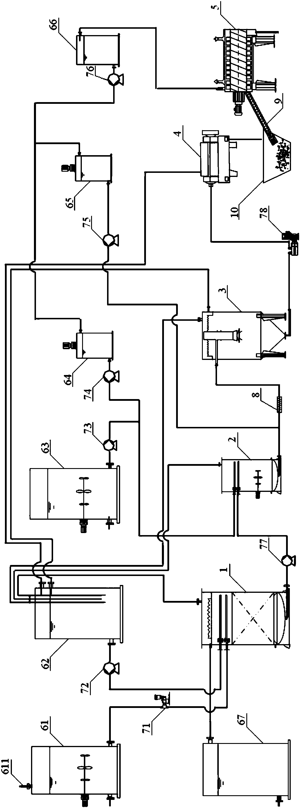
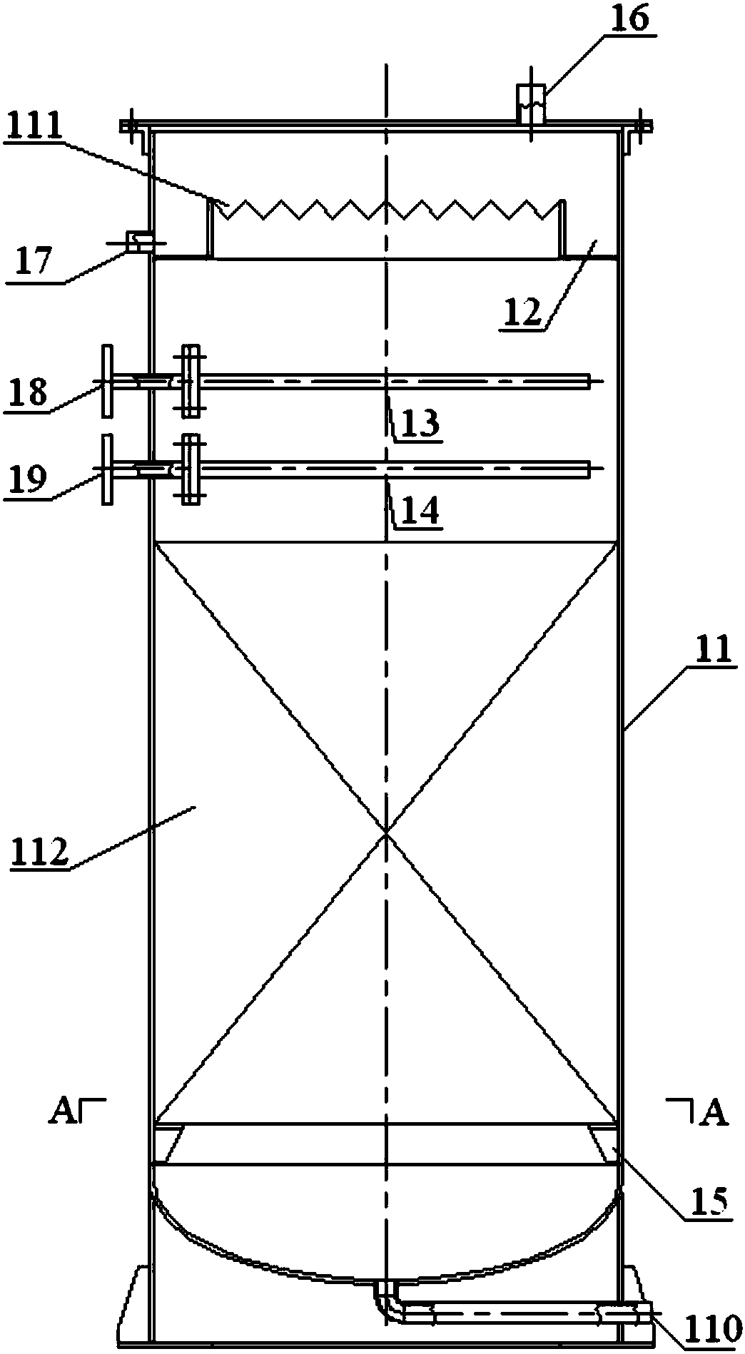
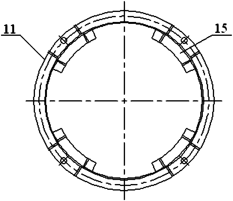
[0098] Combine Figure 1 to Figure 9 As shown, the system for treating spent chloroaluminate ionic liquid catalysts and alkaline wastewater of the present invention includes a hydrolysis reactor 1, a neutralization reactor 2, a flocculation precipitation system, a mechanical dehydration device 4, and a drying device 5; Reactor 1 is used to mix waste ...


PUM


Abstract

The invention provides a system for treating a chloroaluminate ionic liquid spent catalyst and alkaline wastewater. The system comprises a hydrolysis reactor, a neutralization reactor, a flocculationsedimentation system, a mechanical dehydration device and a drying device, wherein the hydrolysis reactor is used for mixing the chloroaluminate ionic liquid spent catalyst with strong brine for hydrolysis reaction; the neutralization reactor is connected to the hydrolysis reactor and is used for mixing acidic hydrolysate generated by hydrolysis reaction with alkali liquor containing the alkalinewastewater for neutralization reaction; the flocculation sedimentation system is connected to the neutralization reactor and is used for fully mixing neutralization liquid generated by neutralizationreaction with a flocculant and carrying out sedimentation separation; the mechanical dehydration device is connected to the flocculation sedimentation system and is used for dehydration treatment of concentrated flocs formed by sedimentation separation; and the drying device is connected to the mechanical dehydration device and is used for drying wet solid residues formed by dehydration treatment.The system can softly eliminate the activity of the spent catalyst, and has good stability and safety of operation.

Description

technical field [0001] The invention belongs to the technical field of petrochemical industry, and in particular relates to a system for treating waste catalysts of chloroaluminate-based ionic liquids and alkaline waste water. Background technique [0002] As the national clean oil product upgrading strategy enters the accelerated promotion period, as an ideal blending component of clean gasoline, the demand for high-octane alkylated oil ushered in explosive growth. Catalytic alkylation using C4 as raw material is the main process for the production of alkylated oil. Most of the existing alkylation processes use two traditional process routes: hydrofluoric acid method and sulfuric acid method. However, the above-mentioned traditional process route uses hydrofluoric acid and sulfuric acid as catalysts, which not only causes huge safety hazards to the process, equipment and personnel, but also creates a large amount of "waste acid slag" and alkali-containing wastewater dischar...

Claims


Application Information

Patent Timeline
IPC IPC(8): B01J19/18B01J19/00C02F1/52C02F1/56C02F1/66C02F11/121C02F11/127C02F11/12C02F11/13C02F103/36
CPCB01J19/00B01J19/1862C02F1/52C02F1/56C02F1/66C02F11/12C02F11/121C02F11/122C02F11/127C02F2001/007C02F2103/365
Inventor 陈春茂刘植昌易忠进张睿梁家豪孟祥海刘海燕徐春明王庆宏
Owner CHINA UNIV OF PETROLEUM (BEIJING)
Why Eureka
Try Eureka