Rear light splitting pupil differential confocal LIBS-mass spectrometry microscopic imaging method and device
A differential confocal and microscopic imaging technology, used in measurement devices, analytical materials, thermal excitation analysis, etc., can solve the problems of low spatial resolution of mass spectrometry detection, large laser focusing spot, and long mass spectrometry imaging time. Achieve universality, expand application fields, and improve the effect of spatial resolution
- Summary
- Abstract
- Description
- Claims
- Application Information
AI Technical Summary
Problems solved by technology
Method used
Image

Examples
Embodiment 1
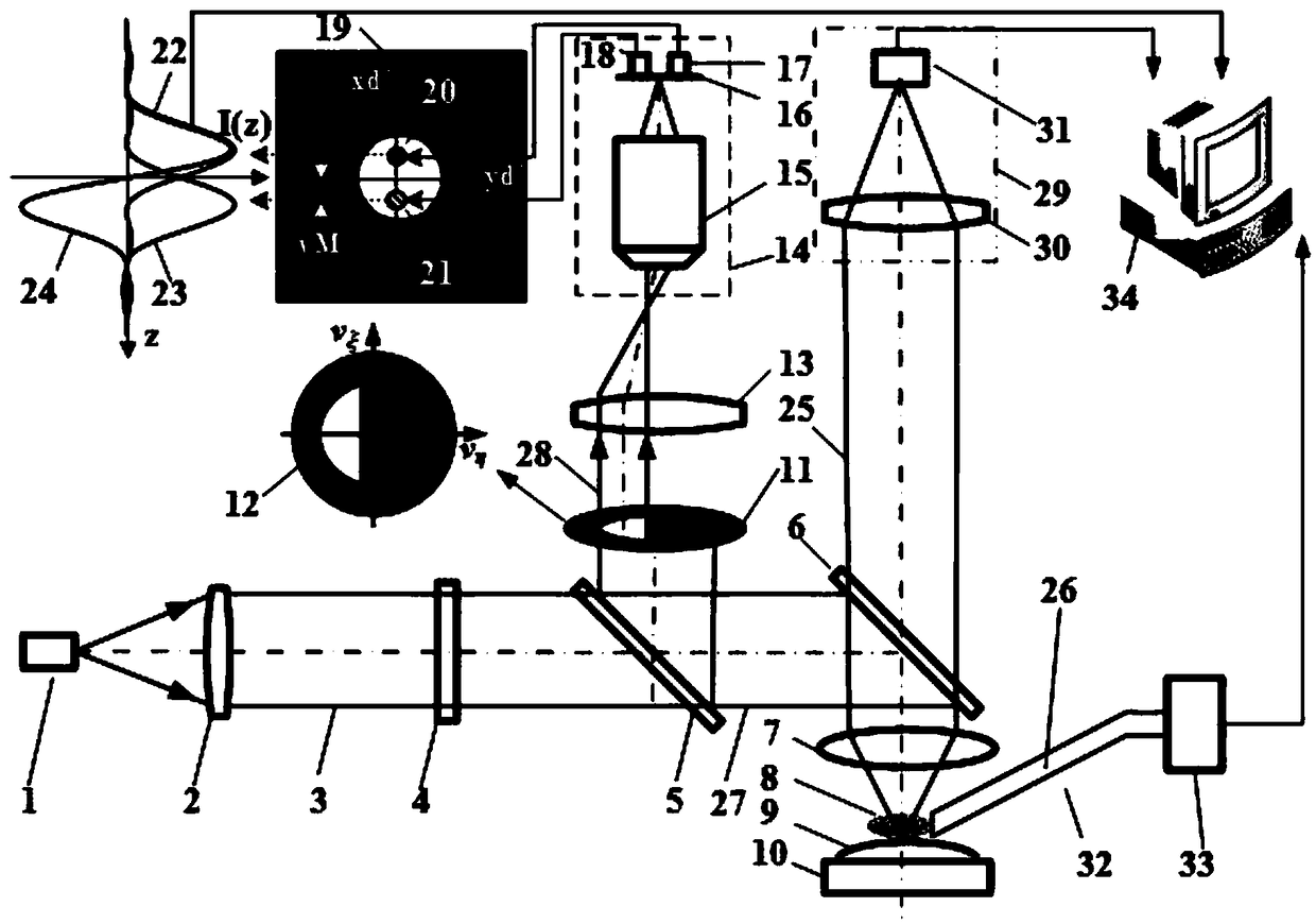
[0046] Such as figure 1 As shown, the collection pupil 11 is placed on the pupil plane of the detection objective lens 13 . The light source system 1 of the excitation beam adopts a point light source, and the excitation beam emitted by the point light source converges on the sample 8 after passing through the collimating lens 2, the compressed focusing spot system 4, the beam splitting prism 5, the dichroic mirror A6 and the measuring objective lens 7 , the computer 34 controls the precise three-dimensional workbench 10 to drive the measured sample 8 to move up and down near the focus of the measuring objective lens 7, and the light reflected by the sample is reflected by the dichroic mirror A6 and reflected by the dichroic prism 5 through the D-type rear pupil 11. The D-type collection pupil 12, the detection objective lens 13, and the relay magnifying lens 14 converge on the two-quadrant detector 16, and the first detection quadrant 17 and the second detection quadrant 18, ...
Embodiment 2
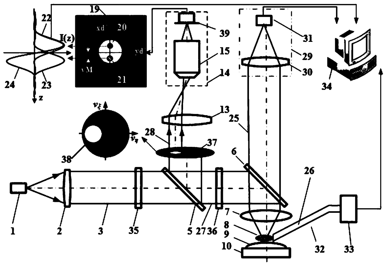
[0055] Such as figure 2 As shown: in the rear split pupil differential confocal LIBS spectrum-mass spectrometer imaging device, the compressed focusing spot system 4 is replaced by a vector beam generation system 35 and a pupil filter 36, and the D-type rear pupil 11 can be replaced by a circular The rear pupil 37 is replaced, and the two-quadrant detector is replaced by a CCD detector 39, wherein the first micro-area of the Airy disk and the second micro-area of the Airy disk detected by the CCD detector are symmetrical about the optical axis.
[0056] All the other are the same as above-mentioned embodiment 1.
Embodiment 3
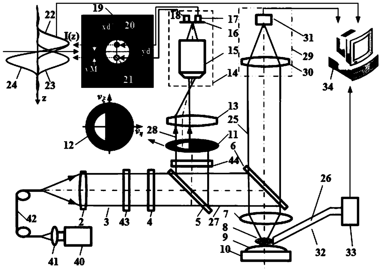
[0058] Such as image 3 As shown: in the post-divided pupil differential confocal LIBS spectrum-mass spectrometer imaging device, the point light source 1 can be replaced by a pulse laser 40, a condenser lens 41, and a light-transmitting optical fiber 42 at the focus of the condenser lens 41. At the same time, the laser An exit beam attenuator 43 is introduced into the focusing system, and a detection beam attenuator 44 is introduced into the rear split pupil differential confocal detection system. The light intensity adjustment system is composed of the exit beam attenuator 43 and the detection beam attenuator 44, which are used to attenuate the focused spot and the spot intensity detected by the two-quadrant detector 16, so as to meet the light intensity requirement when the sample surface is positioned.
[0059] The remaining imaging methods and processes are the same as in Example 1.
PUM
 Abstract
Description
Claims
Application Information
 - R&D
- Intellectual Property
- Life Sciences
- Materials
- Tech Scout
- Unparalleled Data Quality
- Higher Quality Content
- 60% Fewer Hallucinations
Browse by: Latest US Patents, China's latest patents, Technical Efficacy Thesaurus, Application Domain, Technology Topic, Popular Technical Reports.
© 2025 PatSnap. All rights reserved.Legal|Privacy policy|Modern Slavery Act Transparency Statement|Sitemap|About US| Contact US: help@patsnap.com