
Supercritical carbon dioxide cycle cold end waste heat recovery power generation system and operation method

A carbon dioxide and waste heat recovery technology, which is applied in the direction of indirect carbon dioxide emission reduction, steam generation method using heat carrier, steam generation method, etc., can solve the problems of high radiant heat load of boiler furnace, affecting the safe operation of the boiler, and the inability to use the boiler, etc. Achieve the effects of improving power generation efficiency, avoiding overheating, and improving boiler efficiency

Active Publication Date: 2020-06-02
XI AN JIAOTONG UNIV
View PDF4 Cites 0 Cited by
  • Summary
  • Abstract
  • Description
  • Claims
  • Application Information

AI Technical Summary

Problems solved by technology

However, the low-temperature supercritical carbon dioxide is heated by the low-temperature regenerator and the high-temperature regenerator, resulting in a high temperature of the supercritical carbon dioxide at the boiler inlet, which cannot use the heat of the low-temperature flue gas in the flue at the tail of the boiler, resulting in an excessively high exhaust gas temperature of the boiler and a decrease in boiler efficiency. Therefore, the configuration of the supercritical carbon dioxide power cycle system needs to be further optimized; at the same time, due to the high radiation heat load of the boiler furnace, the heat absorption load of superheated carbon dioxide in the boiler is low, and only a single superheated gas cooling wall is arranged in the furnace. The superheated carbon dioxide is overheated, resulting in overheating of the metal wall temperature of the pipeline and affecting the safe operation of the boiler. Therefore, it is necessary to arrange the radiation heating surface in the boiler furnace reasonably; Heat release will cause a lot of cold source loss, so recovering this part of heat is conducive to improving cycle efficiency

Method used


Image

  • Supercritical carbon dioxide cycle cold end waste heat recovery power generation system and operation method

Examples


Embodiment Construction

[0020] The present invention will be described in further detail below in conjunction with the accompanying drawings and specific embodiments.

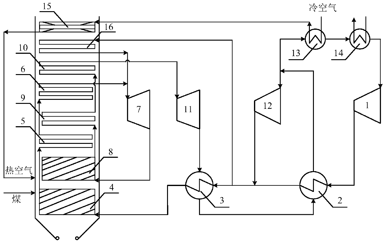
[0021] Such as figure 1 As shown, a supercritical carbon dioxide cycle cold-end waste heat recovery power generation system includes an auxiliary air preheater 13, a precooler 14, a main compressor 1, a low-temperature regenerator 2, a high-temperature regenerator 3, and an overheating regenerator connected in sequence. Hot gas cold wall 4, low temperature superheater 5, high temperature superheater 6, high pressure turbine 7, reheat gas cold wall 8, low temperature reheater 9, high temperature reheater 10 and low pressure turbine 11; recompressor 12, Auxiliary air preheater 13, precooler 14, air preheater 15 and split superheater 16; exhaust gas from low-pressure turbine 11 releases heat in high-temperature regenerator 3 and low-temperature regenerator 2 in sequence, and main compressor 1 exits The low-temperature working fluid abso...


PUM


Abstract

The invention discloses a generation system with waste heat recovery at a supercritical carbon dioxide circulating cold end and an operation method. The system comprises a main compressor, a secondarycompressor, a pre-cooler, a low-temperature heat regenerator, a high-temperature heat regenerator, a boiler, a high pressure turbine, a low pressure turbine and an auxiliary air pre-heater, wherein the boiler comprises an overheating air cooling wall, a secondary hot air cooling wall, a low-temperature over-heater, a low-temperature re-heater, a high-temperature over-heater, a high-temperature re-heater, a shunt over-heater and an air pre-heater; and radiated heat loads of a furnace are borne jointly by two radiation heated faces through layout of the overheated air cooling wall and the secondary hot air cooling wall in the furnace, so overheated supercritical carbon dioxide is prevented from reaching an excess temperature. According to the system and the method disclosed by the invention, a part of low-temperature supercritical carbon dioxide working medium is shunted from an outlet of the secondary compressor into the tail part of the boiler and then smoke energy at low and medium temperature is absorbed by the shunt over-heater, so a smoke emission temperature of the boiler is reduced and boiler efficiency is increased. Cold air is pre-heated with the cold-source supercriticalcarbon dioxide working medium in the auxiliary air pre-heater, so cold-source losses are reduced and thus circulation efficiency is increased and electricity generation efficiency is further increased.

Description

technical field [0001] The invention relates to the technical field of power generation, in particular to a supercritical carbon dioxide cycle cold end waste heat recovery power generation system and an operation method. Background technique [0002] Coal-fired power generation is the main power generation method in my country, but coal combustion emits a large amount of pollutants such as carbon dioxide, sulfur dioxide, and nitrogen oxides, causing global warming and environmental pollution. Therefore, improving the efficiency of thermal power generation is of great significance to my country's energy conservation and emission reduction. In recent years, my country has made great progress in the thermal power generation industry by adopting large-capacity and high-parameter units, various combined cycles, improving operation levels, and shutting down low-capacity and low-efficiency units with large pressure and small capacity. From improving the initial parameters, steam reh...

Claims


Application Information

Patent Timeline
Patent Type & Authority Patents(China)
IPC IPC(8): F01K7/32F01K27/00F22B1/18F22G3/00F23J15/06F23L15/02F22B31/08
CPCF01K7/32F01K27/00F22B1/1807F22B31/08F22G3/00F23J15/06F23L15/02Y02E20/34
Inventor 刘明张旭伟严俊杰种道彤邢秦安刘继平
Owner XI AN JIAOTONG UNIV
Learn More