Method and apparatus for removing sulfur oxides and/or nitrogen oxides from catalytic cracking regeneration flue gas

A technology of sulfur oxides and nitrogen oxides, which is applied in the field of removing pollutants in industrial flue gas and removing sulfur oxides in industrial flue gas, and can solve the problem of the amount of sulfur transfer agent failure transfer aids, and the ineffective reduction reaction. Complete and other problems to achieve the effect of saving equipment investment, improving the utilization rate of heat energy and pressure, and simplifying the process

Active Publication Date: 2019-05-07
CHINA PETROLEUM & CHEM CORP +1
View PDF5 Cites 1 Cited by
  • Summary
  • Abstract
  • Description
  • Claims
  • Application Information

AI Technical Summary

Problems solved by technology

[0005] Due to the mixed use, the sulfur transfer agent goes through the same path as the catalytic cracking catalyst, which is tested in the cycle between oxidizing atmosphere and reducing atmosphere: the sulfate formed on the sulfur transfer agent in the regenerator with high temperature and oxidizing atmosphere needs to have Good stability; when the mixture enters the reducing atmosphere, the reaction involving sulfate is only one of the many reactions involving multi-carbon number hydrocarbon cracking, isomerization, condensation, polycondensation, etc., involving sulfate and The reduction reaction of metal sulfide is not complete, and the result of long-term accumulation will lead to the failure of the sulfur transfer agent and the dosage of the transfer aid

Method used


Image

  • Method and apparatus for removing sulfur oxides and/or nitrogen oxides from catalytic cracking regeneration flue gas
  • Method and apparatus for removing sulfur oxides and/or nitrogen oxides from catalytic cracking regeneration flue gas
  • Method and apparatus for removing sulfur oxides and/or nitrogen oxides from catalytic cracking regeneration flue gas

Examples


specific Embodiment approach

[0040] A method for removing sulfur oxides and / or nitrogen oxides in catalytic cracking regenerated flue gas provided by the present invention comprises:

[0041] (1) In the catalytic cracking regenerator, at a temperature of 650°C to 750°C, the desulfurization and denitrification additives and the catalytic cracking catalyst are in contact with the regenerated flue gas, and the sulfur oxides in it are adsorbed and removed, and the sulfur oxides in it are decomposed and removed. Nitrogen oxides, the desulfurization and denitrification additives are modified magnesium aluminum spinel and / or modified hydrotalcite;

[0042] (2) introducing the raw desulfurization and denitrification auxiliary agent and the regenerated catalytic cracking agent after the reaction in step (1) into the catalytic cracking reactor, contacting with catalytic cracking raw materials, and performing catalytic cracking reaction;

[0043] (3) Introduce the raw desulfurization and denitrification auxiliary ag...

Embodiment 1

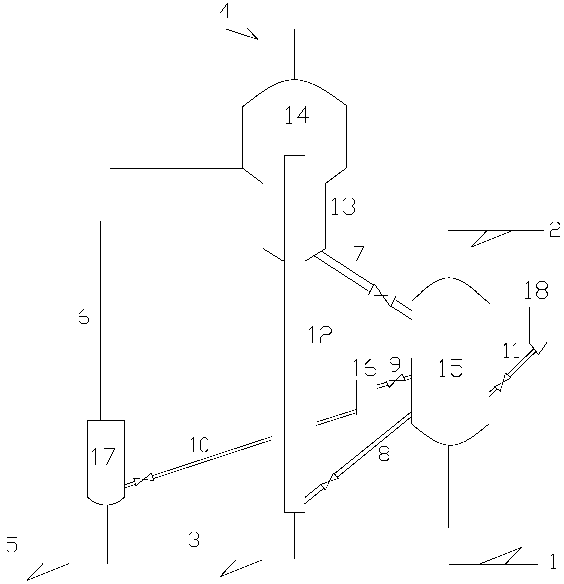
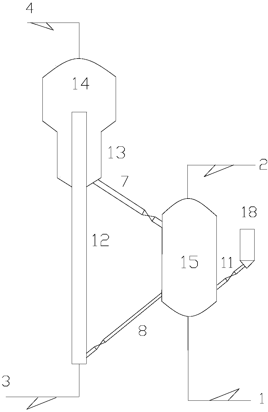
[0094] Adopt the catalytic cracking test device that the present invention provides with auxiliary agent regenerator, process flow chart is as attached figure 1 shown. The catalytic cracking reaction raw materials are the same as in Example 1, and the catalyst is an industrial balancer for catalytic cracking catalyst CGP-C.

[0095] In the catalytic cracking test device, the catalytic cracking reaction and regeneration conditions are the same as those of Comparative Example 1. The auxiliary agent regenerator adopts a riser reactor, and the packing density of the catalyst in the riser is 20kg / m 3 , the reaction time is 2.5s, the reaction temperature is 520°C, the reducing gas fed into the auxiliary agent regenerator is the dry gas from the catalytic cracking unit, and the regenerated catalytic cracking catalyst is directly returned to the stripping section of the catalytic cracking reaction part, The mass ratio of the catalyst entering the catalytic cracking reaction part to ...

Embodiment 2

[0097] The catalytic cracking test device, catalytic cracking reaction raw material and method used are the same as in Example 1. The operating conditions of auxiliary agent regenerator and catalytic cracking reaction regeneration part are the same as embodiment 1.

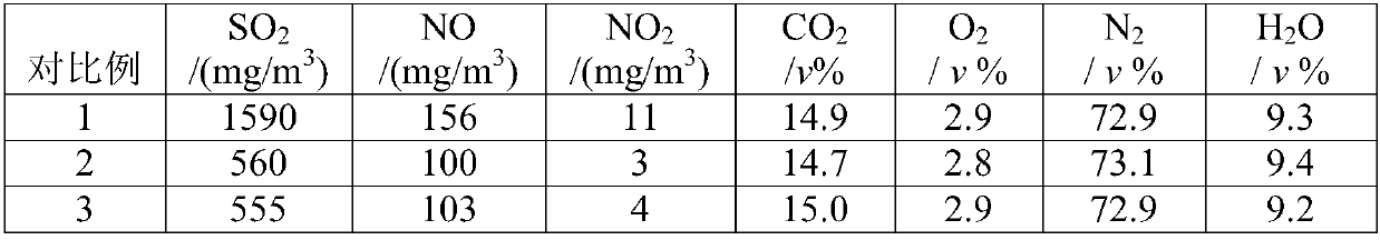
[0098] The difference from Example 1 is that the catalyst is the industrial balancer of the catalytic cracking catalyst CGP-C and the desulfurization and denitrification auxiliary agent C-magnesium aluminum. The mass fraction of the desulfurization and denitrification auxiliary agent in the mixed catalyst is 3.0wt%, and the regeneration is measured after the operation is stable. The composition of the exhaust gas is shown in Table 3.


PUM


Abstract

The invention relates to a method and an apparatus for removing sulfur oxides and / or nitrogen oxides from catalytic cracking regeneration flue gas. The method comprises that in a catalytic cracking regenerator, a desulfurization and denitration auxiliary agent and a catalytic cracking catalyst contact flue gas at a temperature of 650-750 DEG C to remove sulfur oxides and nitrogen oxides from the flue gas; one part of the mixture after the reaction is introduced into a catalytic cracking reactor; the other part of the mixture after the reaction is introduced into an auxiliary agent regenerator,and reacts with reducing gas at a temperature of 450-650 DEG C so as to be regenerated; and the gas-solid stream in the auxiliary agent regenerator is subjected to gas-solid separation, the separatedgas phase is subjected to further subsequent treatment, and the separated regenerated desulfurization and denitration auxiliary agent and the catalytic cracking catalyst return to the catalytic cracking regenerator so as to be recycled. According to the present invention, with the method, the regeneration depth of the spent desulfurization and denitration auxiliary agent is enhanced by the auxiliary agent regenerator so as to ensure the flue gas treatment effect and prolong the service life of the auxiliary agent; and compared with the newly constructed flue gas treatment device, the apparatus of the present invention can simplify the process, easily improve the utilization efficiency of heat energy and pressure, and save the equipment investment.

Description

technical field [0001] The invention relates to a method for removing pollutants in industrial flue gas, more specifically, relates to a method for removing sulfur oxides in industrial flue gas at high temperature, and belongs to the technical field of flue waste gas comprehensive treatment. Background technique [0002] The methods to control the sulfur emission from fluidized catalytic cracking regeneration flue gas mainly include the selection of high-quality crude oil, raw material pretreatment, flue gas treatment and sulfur oxides (SO for short). x ) transfer technology. [0003] Based on source and cost considerations, refineries have little choice for crude oil; raw material pre-hydrogenation and flue gas treatment need to increase equipment construction costs, high energy consumption, high operating costs, but strong applicability, good investment economy, suitable for processing High sulfur crude oil; the use of sulfur oxide transfer agent can control SO in FCC flu...

Claims


Application Information

Patent Timeline
Patent Type & Authority Applications(China)
IPC IPC(8): B01D53/86B01D53/60
CPCY02A50/20
Inventor 郭大为张久顺侯栓弟毛安国何金龙李学锋李强常学良张春城张晨昕王巍武传朋
Owner CHINA PETROLEUM & CHEM CORP
Why Eureka
Try Eureka