Back electrode, solar battery, and preparation methods of back electrode and solar battery

A solar cell and back electrode technology, which is applied in the manufacture of circuits, electrical components, and final products, can solve the problems that it is difficult to make great progress, it is difficult to achieve effective improvement, and it is impossible to achieve large-scale improvement, so as to reduce the area of ​​​​the dead zone , increase the area, avoid the effect of restriction

Pending Publication Date: 2019-06-14
上海祖强能源有限公司
View PDF0 Cites 2 Cited by
  • Summary
  • Abstract
  • Description
  • Claims
  • Application Information

AI Technical Summary

Problems solved by technology

[0007] Limited by the limitations of the existing technological level and the consideration of cost control factors, the width and accuracy of mechanical scribing can only be maintained at a certain level, and substantial improvements cannot be achieved in the short term
The laser scribing process has high requirements on the light transmittance of the substrate, laser type, laser energy, etc., and it is difficult to achieve effective improvement, and laser scribing will cause certain damage to the film layer and the substrate
[0008] Reducing the dead zone area and increasing the effective photoelectric conversion area is an important factor to improve the conversion efficiency of CIGS thin film solar cell modules. By reducing the width of laser and mechanical scribe lines and improving the precision to reduce the dead zone area, the short-term difficult to make much progress

Method used


Image

  • Back electrode, solar battery, and preparation methods of back electrode and solar battery
  • Back electrode, solar battery, and preparation methods of back electrode and solar battery
  • Back electrode, solar battery, and preparation methods of back electrode and solar battery

Examples


no. 1 approach

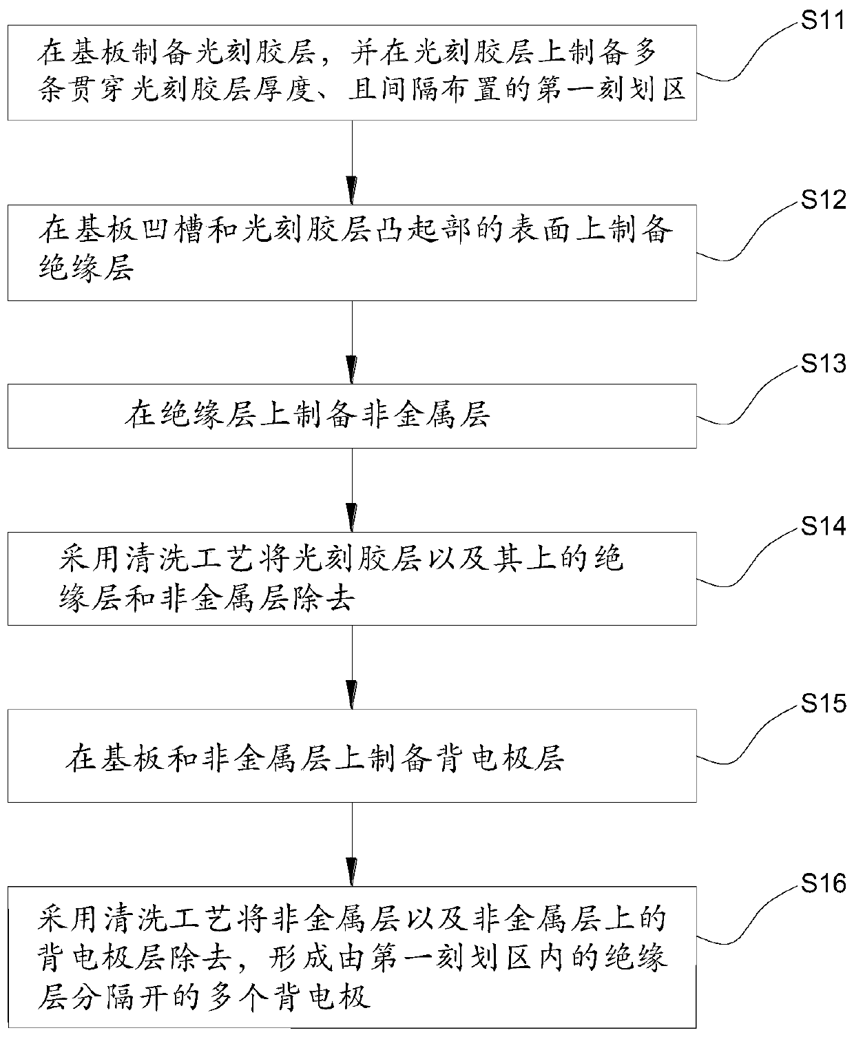
[0052] figure 2 It is the preparation flowchart of solar cell back electrode in the present invention. Such as figure 2 Shown, the preparation method of solar cell back electrode of the present invention comprises the following steps:

[0053] S11 , preparing a photoresist layer 2 on the substrate 1 , and preparing a plurality of first scribed regions penetrating through the thickness of the photoresist layer 2 and arranged at intervals on the photoresist layer 2 . Specifically, the multiple first scoring areas are distributed in an array.

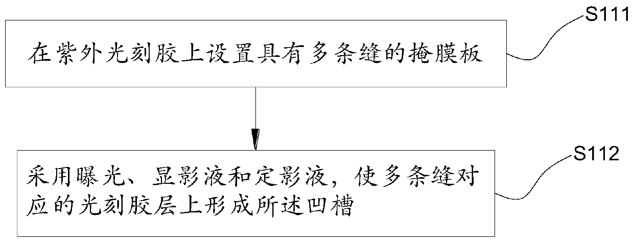
[0054] Such as image 3 As shown, the specific method for preparing the first scribed region on the photoresist layer 2 is as follows:

[0055] S111, setting a mask plate with a plurality of slits on the photoresist;

[0056]S112. Form the first scribed area by means of exposure and development, and obtain the following Figure 4 Structure.

[0057] Specifically, the photoresist can be selected from ultraviolet photoresist. First...

no. 2 approach

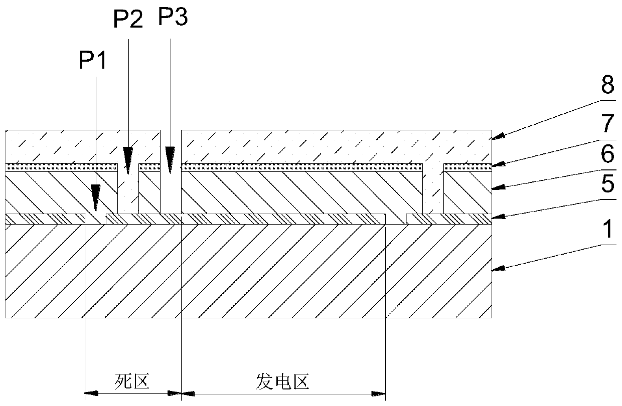
[0070] Figure 9 It is a structure diagram corresponding to step S16 of the preparation method provided by the embodiment of the present invention, that is, a schematic diagram of the structure of the back electrode of the solar cell.

[0071] A back electrode of a solar cell, prepared by the method for preparing a back electrode of a solar cell as described in the first embodiment.

no. 3 approach

[0073] Figure 10 Is the preparation flow chart of solar cell in the present invention, as Figure 10 Shown, the preparation method of solar cell of the present invention comprises the following steps:

[0074] S21. Prepare a solar back electrode by using the method as described in the first embodiment.

[0075] S22, preparing an absorption layer 6 on the back electrode. Specifically, a copper indium gallium selenide absorption layer is prepared on the above-mentioned back electrode by a co-evaporation method.

[0076] The copper indium gallium selenide absorption layer can also be prepared by sputtering selenization method, spin coating and other methods.

[0077] Copper indium selenide and copper gallium selenide can also be used to prepare the absorbing layer.

[0078] S23. Prepare a cadmium sulfide layer 7 on the absorption layer 6; specifically, prepare the cadmium sulfide layer 7 by using a chemical water bath deposition method. It can also be prepared by vacuum spu...


PUM


Abstract

The invention discloses a back electrode, a solar battery, and preparation methods of the back electrode and the solar battery. The preparation method of the solar battery back electrode comprises thefollowing steps of preparing a photoresist layer on a substrate, preparing a plurality of first graving regions which penetrate through the thickness of the photoresist layer and are arranged at intervals on the photoresist layer, preparing an insulating layer on the surfaces of the substrate and the photoresist layer, preparing a nonmetal layer on the insulating layer, removing the photoresist layer and the insulating layer and the nonmetal layer on the photoresist layer by a cleaning process, preparing a back electrode layer on the substrate and the nonmetal layer, and removing the nonmetallayer and the back electrode layer on the nonmetal layer by a cleaning process. According to the method, division of the back electrode is completed by replacing laser graving with a photetching technology, so that damage of the laser graving to the substrate can be avoided; and insulating medium filling is performed in graving lines of the first graving regions (P1), so that the area of an deadregion can be reduced, the area of a power generation region can be increased, and the power generation efficiency can be improved.

Description

technical field [0001] The invention relates to the field of photovoltaic technology, in particular to a method for preparing a back electrode of a solar cell, a back electrode prepared by the method, a method for preparing a solar cell, and a solar cell prepared by the method. Background technique [0002] In the preparation process of existing copper indium gallium selenide thin film solar cells, metal molybdenum is usually used as the back electrode of the cell. In order to achieve high-voltage, low-current power output of CIGS battery components, laser or mechanical scribing is introduced to cut the back electrode, front electrode and other functional film layers, and divide the entire battery into multiple sub-battery units. There are series and parallel relationships among the sub-batteries. [0003] Laser or mechanical scribing is achieved by removing the corresponding film layer, so it will inevitably cause the scribed line area and the area between the scribed line...

Claims


Application Information

Patent Timeline
Patent Type & Authority Applications(China)
IPC IPC(8): H01L31/0224H01L31/18
CPCY02P70/50
Inventor 赵树利杨立红郭逦达
Owner 上海祖强能源有限公司
Why Eureka
Try Eureka