Super-resolution microscope system of small-size plasma nano-particle detection

A nanoparticle and microscopic system technology, applied in individual particle analysis, particle and sedimentation analysis, measurement devices, etc., can solve the problems of low detection resolution, unstable signal, and high sample preparation requirements, achieve high resolution, reduce Experiment cost, effect of good structural details

Active Publication Date: 2019-07-30
JINAN UNIVERSITY
View PDF7 Cites 2 Cited by
  • Summary
  • Abstract
  • Description
  • Claims
  • Application Information

AI Technical Summary

Problems solved by technology

At present, there are mainly three types of detection methods for small-sized plasmonic nanoparticles. The first type mainly uses the interaction between particles and materials to perform small detection, such as atomic force microscopy (AFM) using the interaction force between atoms, and the interaction between electrons and matter. Scanning electron microscope (SEM) and transmission electron microscope (TEM), etc.; the second type of method mainly uses the scattering characteristics of nanoparticles for observation, such as dark field microscopy (DFM); the third type uses fluorescent substances for specific Indirect detection with markers is mainly based on stimulated radiation depletion (STED), photoactivated localization microscopy (PALM) and structured illumination microimaging (SIM). However, the above detection methods are in practical application There are problems such as high sample preparation requirements (first category), low detection resolution (second category), and unstable signal (third category).

Method used


Image

  • Super-resolution microscope system of small-size plasma nano-particle detection
  • Super-resolution microscope system of small-size plasma nano-particle detection
  • Super-resolution microscope system of small-size plasma nano-particle detection

Examples


Embodiment Construction

[0028] The present invention will be further described below in conjunction with drawings and embodiments.

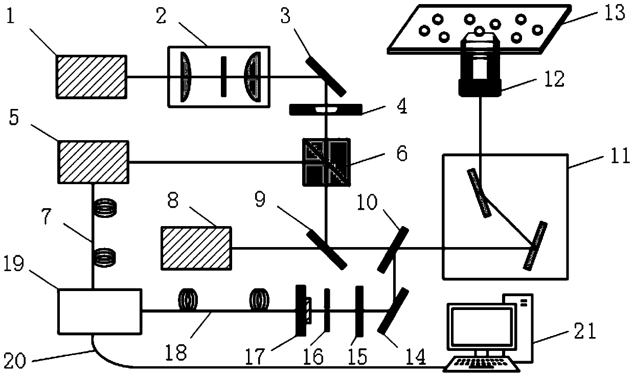
[0029] see figure 1 , a super-resolution microscopy system based on plasmonic nanoparticle detection, including: a first laser 1, a filter unit 2, a first silver mirror 3, a phase plate 4, a second laser 5, a polarization-dependent beam splitter 6, a second Three lasers 8, a dichroic mirror 9, a semi-reflective and semi-transparent glass 10, a vibrating mirror unit 11, a microscope objective lens 12, a displacement platform 13, a second silver mirror 14, a filter 15, a first pinhole 16, Photomultiplier tube 17, lock-in amplifier 19 and terminal 21; the Gaussian suppressed light generated by the first laser 1 is input to the filter unit 2, and after being spatially filtered by the filter unit 2, it is input to the first silver reflector 3 and the phase plate 4, and then passed through The phase plate 4 is phase-modulated to generate ring-shaped suppressed light; the loc...


PUM

PropertyMeasurementUnit
sizeaaaaaaaaaa

Abstract

The invention discloses a super-resolution microscope system of small-size plasma nano-particle detection. The super-resolution microscope system is mainly composed of a first laser, a filtering unit,a first silver reflector, a phase plate, a polarization-dependent beam splitter, a third laser, a dichroscope, a semi-reflective and semi-transparent glass slide, a galvanometer unit, a microobjective, a displacement platform, a second silver reflector, an optical filter, a first pinhole, a photomultiplier, a lock-in amplifier and a terminal, wherein the Gaussian suppression light generated by the first laser is input to the filtering unit, and the Gaussian suppression light is input to the first silver reflector and the phase plate after passing through the filtering unit, and the Gaussian suppression light generate annular suppression light through the phase plate; and the lock-in amplifier controls the second laser to generates Gaussian modulated light. The super-resolution microscopesystem disclosed by the invention has the properties of low suppression power, ultra high resolution, no photobleaching, high signal contrast ratio, extremely high reproducibility and long-lasting observation, and can realize the microimaging of small-size plasma nano-particles in a complex biological environment.

Description

technical field [0001] The invention relates to the technical field of super-resolution microscopic imaging, in particular to an all-optical switch regulation technology based on the nonlinear characteristics of small-sized plasma nanoparticles and a weak signal extraction technology of a lock-in amplifier. Background technique [0002] Plasmonic nanoparticles have a surface plasmon effect due to the presence of a large number of freely oscillating electrons on the surface, and are widely used in optical devices, biomarkers, solar cells, non-volatile memory, nanotechnology and other fields. At the same time, small-sized plasmonic nanoparticles In terms of material characterization and biomicroscopic imaging, it has the advantages of small size and obvious plasma effect. At present, there are mainly three types of detection methods for small-sized plasmonic nanoparticles. The first type mainly uses the interaction between particles and materials to perform small detection, su...

Claims


Application Information

Patent Timeline
Patent Type & Authority Applications(China)
IPC IPC(8): G01N21/47G01N15/10
CPCG01N21/47G01N15/10G01N2015/1006
Inventor 李向平徐坚纪子衡张天悦
Owner JINAN UNIVERSITY
Why Eureka
Try Eureka