Microorganism denitrification treatment device

A treatment device and microbial technology, applied in the direction of biological treatment devices, sustainable biological treatment, biological water/sewage treatment, etc., can solve the problems of destroying the balance of denitrification conversion reaction, low denitrification efficiency, small specific surface area, etc., and achieve improvement Adhering species and biomass, improving denitrification efficiency, and high degree of intelligence

Inactive Publication Date: 2019-08-23
JIANGSU FRONTIER ELECTRIC TECH +2
View PDF6 Cites 0 Cited by
  • Summary
  • Abstract
  • Description
  • Claims
  • Application Information

AI Technical Summary

Problems solved by technology

However, with the growth of microorganisms, the biofilm gradually thickens, and an anaerobic zone is easily formed inside the too thick biofilm, which destroys the balance of the denitrification conversion reaction in the device. Therefore, it is necessary to aerate the microbial carrier and properly adjust the aeration Strength, so that the surface of the microbial carrier maintains a moderate biofilm thickness
[0004] Existing aeration devices usually perform aeration with a fixed frequency and a fixed aeration intensity, which requires manual measurement of the dissolved oxygen in the box, and real-time adjustment of the aeration frequency and aeration intensity according to the measured data. The amount of aeration is large, and the aeration amount cannot be accurately controlled. Too little aeration amount will lead to too thick biofilm, which will greatly affect the quality of sewage treatment. Too much aeration amount will cause waste of energy
Moreover, the existing microbial carrier is spherical, difficult to fix and has a small specific surface area, low nitrogen removal efficiency, and the microorganisms inside it are easily washed away by sewage

Method used


Image

  • Microorganism denitrification treatment device
  • Microorganism denitrification treatment device
  • Microorganism denitrification treatment device

Examples


Embodiment 1

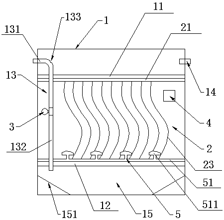
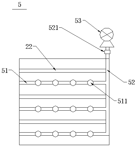
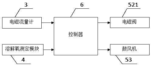
[0023] Example 1: please refer to figure 1 and image 3 , figure 1 It is an overall schematic diagram of a microbial denitrification treatment device according to an embodiment of the present invention, image 3 It is a system schematic diagram of an embodiment of the present invention. The present invention proposes a microbial denitrification treatment device, including a box body 1, a plurality of microbial carriers 2, an electromagnetic flowmeter 3, a dissolved oxygen measurement module 4, an aeration device 5 and a controller 6, and the box body 1 has a plurality of upper A frame 11 , a plurality of lower frames 12 , a water guide pipe 13 and a water outlet 14 .

[0024] A plurality of upper frames 11 located on the same horizontal plane are arranged horizontally and close to the upper port of the box body 1, and the two ends of the upper frames 11 are respectively fixedly connected to the left and right sides of the box body 1, and the plurality of lower frames 12 loc...

Embodiment 2

[0030] Embodiment 2: On the basis of Embodiment 1, the box body 1 also has a mud collection area 15, the mud collection area 15 is located at the lower end of a plurality of lower frames 12, and the mud collection area 15 has two inclined plates 151 arranged symmetrically. The outer sides of one swash plate 151 are fixedly connected with the left and right sides of the box body 1 respectively, and the inner sides of the two slant plates 151 are fixedly connected with the bottom surface of the box body 1 respectively. Sewage treated by the microbial carrier 2 will leave sludge, and the sludge will settle into the sludge collecting area 15, where the two sloping plates 151 can collect the sludge, making it easier to clean. A mud discharge device and a backwashing device can be set in the mud collection area 15, which can be used for forward suction and discharge of mud through the mud discharge device, and can also be reversely flushed in the mud collection area 15 through the ba...

Embodiment 3

[0032] Embodiment 3: On the basis of Embodiment 1 or Embodiment 2, the water guide pipe 13 has a perforation 133, and the perforation 133 is located at the junction of the horizontal pipe 131 and the vertical pipe 132, and the sewage enters the box body 1 from the regulating tank. The height of the liquid level is lower than that of the tank 1. If the amount of sewage entering the tank 1 is small, the sewage may flow back into the regulating tank, and the perforation 133 can destroy the siphon, effectively avoid the siphon phenomenon, and prevent Sewage backflow.

[0033] Preferably, the ratio of the total volume of the porous wire 23 to the total volume of the box 1 is 50%-60%, that is, the filling rate of the porous wire 23 is 50%-60%, and this range includes 50% and 60%. The porous wire 23 with this filling rate has lower running cost and better treatment effect.

[0034] Please refer to Figure 4 , Figure 4 It is a schematic diagram of three microbial denitrification t...


PUM


Abstract

The invention discloses a microorganism denitrification treatment device. The microorganism denitrification treatment device comprises a box body, a plurality of microorganism carriers, an electromagnetic flowmeter, a dissolved oxygen determination module, an aeration device and a controller, and a plurality of upper frames, a plurality of lower frames, a water guide pipe and a water outlet are arranged in the box body. The upper frames positioned on the same horizontal plane are transversely arranged and close to the upper port of the box body, two ends of each of upper frames are fixedly connected with the left surface and the right surface of the box body respectively, the lower frames which are positioned on the same horizontal plane are transversely arranged and close to the bottom ofthe box body, and two ends of each of the lower frames are fixedly connected with the left surface and the right surface of the box body respectively. Each microorganism carrier comprises an upper fixing rod, a lower fixing rod and a plurality of porous wires, and the upper fixing rod and the lower fixing rod, which are arranged transversely, of each microorganism carrier are horizontally arranged and are positioned on the same vertical plane. By the aeration device in the invention, accurate aeration can be realized, intelligent degree is high, and energy saving and consumption reduction areachieved.

Description

technical field [0001] The invention belongs to the technical field of sewage treatment, and in particular relates to a microbial denitrification treatment device. Background technique [0002] In recent years, with the development of industry and agriculture, the problem of water pollution has become increasingly prominent. Total nitrogen and COD are the main pollutants that cause water quality to exceed the standard. The impact of water pollution on the environment has attracted great attention in the field of environmental protection worldwide. The traditional denitrification process can be divided into physical chemical denitrification method and biological denitrification method. Among them, physical and chemical denitrification methods include: break point chlorination method, chemical precipitation method, adsorption method, ion exchange method, stripping method, gas stripping method, liquid membrane method, electrodialysis method and wet catalytic oxidation method, e...

Claims


Application Information

Patent Timeline
Patent Type & Authority Applications(China)
IPC IPC(8): C02F3/30C02F3/34C02F7/00C02F101/16
CPCC02F3/301C02F3/302C02F3/34C02F7/00C02F2101/16C02F2203/006C02F2209/22C02F2209/40Y02W10/10
Inventor 祁建民孙和泰华伟黄治军张磊傅高健王林王明李海涛疏雪峰黄轶康
Owner JIANGSU FRONTIER ELECTRIC TECH
Why Eureka
Try Eureka