
Crude gas waste heat recycling and use system and method

A waste heat recovery system and waste heat recovery technology, applied in the field of coke oven gas waste heat recovery, can solve problems such as unreasonable use of waste heat from waste gas, and achieve the effects of eliminating hidden dangers in production safety, significant economic benefits, and saving coke oven gas

Pending Publication Date: 2019-09-17
WUHAN FRONT IND EQUIP TECH
View PDF0 Cites 1 Cited by
  • Summary
  • Abstract
  • Description
  • Claims
  • Application Information

AI Technical Summary

Problems solved by technology

[0005] In order to solve the technical problem of unreasonable utilization of waste heat of raw coal gas in the prior art, the present invention provides a system and method for recovering and utilizing waste heat of raw coal gas, which can efficiently recycle and utilize waste heat in raw coal gas

Method used


Image

  • Crude gas waste heat recycling and use system and method
  • Crude gas waste heat recycling and use system and method

Examples


Embodiment 1

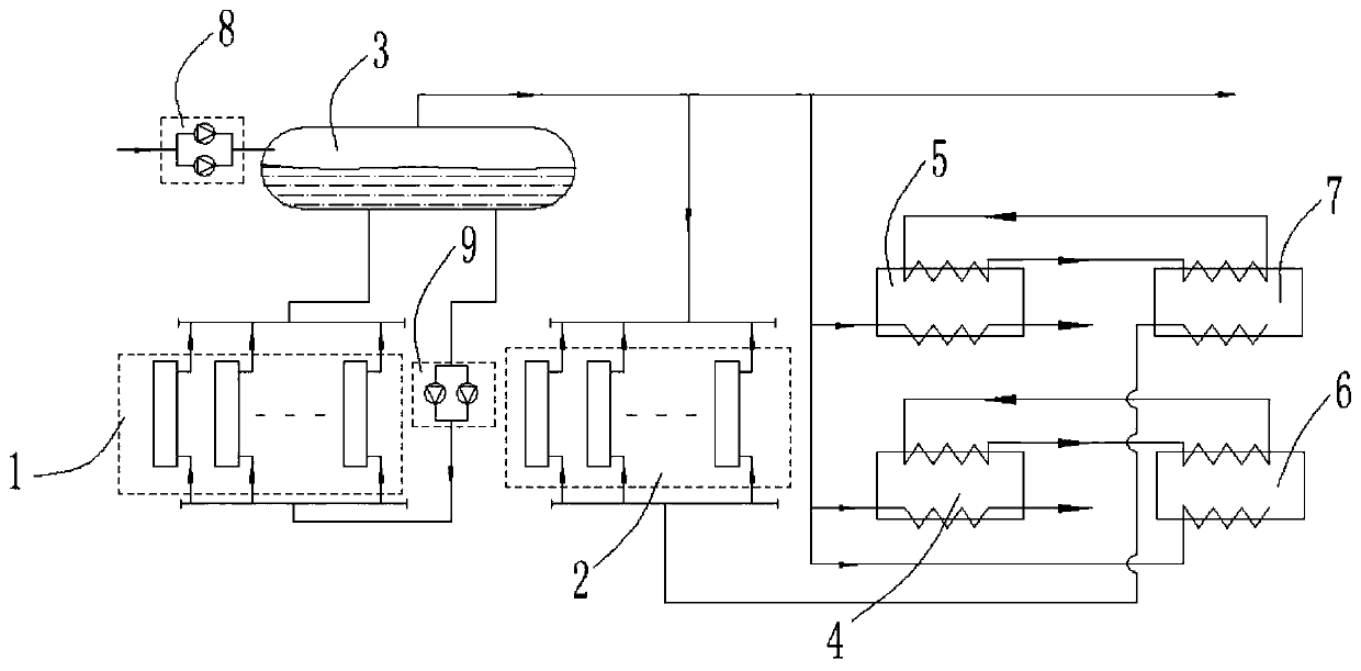
[0037] Embodiment 1 of the present invention provides a high-temperature raw gas waste heat recovery and utilization system, such as figure 2 shown.

[0038]The raw gas waste heat recovery and utilization system of the present invention includes two parts: a waste heat recovery system and a waste heat utilization system. The waste heat recovery system includes a saturated steam heat exchanger group 1, a superheated steam heat exchanger group 2, and a steam drum 3 with a steam-water separator And feed water pump group 8 and circulating water pump group 9; waste heat utilization system includes condensed ammonia water heater 4, condensed oil-rich heater 5, ammonia distillation tower 6 and debenzene tower 7; the water inlet of saturated steam heat exchanger group 1 passes through the circulation The water pump group 9 is connected to the water outlet of the steam drum 3, the water outlet of the saturated steam heat exchanger group 1 is connected to the first water inlet of the s...

Embodiment 2

[0045] Embodiment 2 of the present invention provides a method for recovering waste heat from raw coal gas, comprising the following steps:

[0046] Step 1. The water in the steam drum 3 is transported to the saturated steam heat exchanger group 1 through the circulating water pump group 9, and the mixture of saturated steam and water generated after heat exchange by the saturated steam heat exchanger group 1 passes through the steam drum 3. The first water inlet returns to the steam drum 3;

[0047] Step 2: Transport part of the saturated steam generated in the steam drum 3 through the gas-liquid separator to the waste heat utilization system through the steam pipe network to provide heat energy for the condensed ammonia water heater 4, the condensed oil-rich heater 5 and the ammonia distillation tower 6; The condensed water separated after heat exchange between the steam and the condensed ammonia water heater 4 and the condensed oil-rich heater 5 is returned to the steam dru...


PUM


Abstract

The invention discloses a crude gas waste heat recycling and use system and method. The crude gas waste heat recycling and use system comprises a waste heat recycling system and a waste heat use system, wherein the waste heat recycling system comprises a saturated steam heat exchanger group, a superheated steam heat exchanger group, a steam pocket with a steam-water separator, a circulation water pump group and a water supply pump group; and the waste heat use system comprises a condensed ammonium hydroxide heater, a condensed rich oil heater, an ammonia evaporation tower and a debenzolization tower. The crude gas waste heat recycling and use system and the waste heat recycling and use method disclosed by the invention are not only environment-friendly and energy-saving, but also remarkable in economic benefit, both the waste heat utilization rate of a company can be increased, and carbon emission and waste gas discharge can be reduced, and in addition, steam can be supplied outside to make economic values.

Description

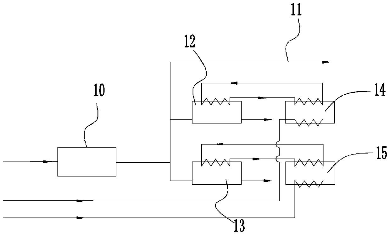
technical field [0001] The invention belongs to the technical field of waste heat recovery of coke oven raw gas, and in particular relates to a waste heat recovery system and method of raw gas. Background technique [0002] In the coking industry, the coke oven emits a large amount of high-temperature raw gas. The gas temperature is between 700-800°C. The gas is cooled by spraying, so that the gas temperature drops from 700-800°C to 80-90°C, and the heat is wasted. In addition, at present, the chemical production workshop of the coking industry generally uses a tubular heating furnace to heat rich oil and ammonia water. The heating furnace burns coke oven gas to heat the medium in the tube. The exhaust gas temperature of the heating furnace reaches 300 ° C, and the thermal efficiency is low. It is being eliminated by the country. High energy consumption equipment. Its process is as figure 1 As shown, the raw coal gas with a temperature between 700 and 800°C transported fro...

Claims


Application Information

Patent Timeline
IPC IPC(8): C10K1/12C10K1/00F27D17/00F22B1/18F22G1/00
CPCC10K1/121C10K1/001C10K1/002C10K1/004C10K1/005F27D17/004F22B1/18F22G1/02Y02P20/129Y02P10/25Y02P20/10
Inventor 宋旭勇李哲
Owner WUHAN FRONT IND EQUIP TECH
Learn More