ZnO modified SnO2-based perovskite solar cell and preparation method thereof

A solar cell and perovskite technology, which is applied in semiconductor/solid-state device manufacturing, circuits, photovoltaic power generation, etc., can solve problems such as energy level mismatch, film quality reduction, and battery efficiency improvement

Active Publication Date: 2019-10-08
COLLEGE OF SCI & TECH NINGBO UNIV
View PDF8 Cites 0 Cited by
  • Summary
  • Abstract
  • Description
  • Claims
  • Application Information

AI Technical Summary

Problems solved by technology

[0003] However, SnO 2 There is still a problem of energy level mismatch with the ITO interface, and the rough ITO surface will cause SnO 2 The quality of film formation is reduced, which limits the further improvement of battery efficiency

Method used


Image

  • ZnO modified SnO2-based perovskite solar cell and preparation method thereof
  • ZnO modified SnO2-based perovskite solar cell and preparation method thereof
  • ZnO modified SnO2-based perovskite solar cell and preparation method thereof

Examples


Embodiment 1

[0033] A kind of ZnO modified SnO 2 A method for preparing a base perovskite solar cell, comprising the steps of:

[0034] Step ①: Mix the ZnO nanoparticle aqueous solution and ammonia water to make a ZnO precursor solution, and then filter it with a 0.22 μm PTFE filter head, wherein the mass fraction of ZnO nanoparticles in the ZnO nanoparticle aqueous solution is 20%, and the volume fraction of ammonia water is 50%, The volume ratio of ZnO nanoparticles aqueous solution and ammonia water is 1:25;

[0035] Spin-coat 30 μL of ZnO precursor solution on the surface of the conductive glass layer (ITO) and then anneal to form a 20nm-thick ZnO modified layer. The rotation speed is 5000rpm / 30s, spin-coating for 30s, the annealing temperature is 200°C, and the annealing time is 15 minutes;

[0036] Step ②: SnO 2 Nanoparticle aqueous solution mixed with ammonia water to make SnO 2 Precursor solution, and then filtered with 0.22μm PTFE filter head, in which SnO 2 SnO in nanoparticl...

Embodiment 2

[0058] see Figure 4 , the difference between this embodiment and embodiment 1 is that SnO 2 The thickness of the electron transport layer was 60 nm.

Embodiment 3

[0060] see Figure 5 , the difference between this embodiment and embodiment 1 is that SnO 2 The thickness of the electron transport layer was 40 nm.

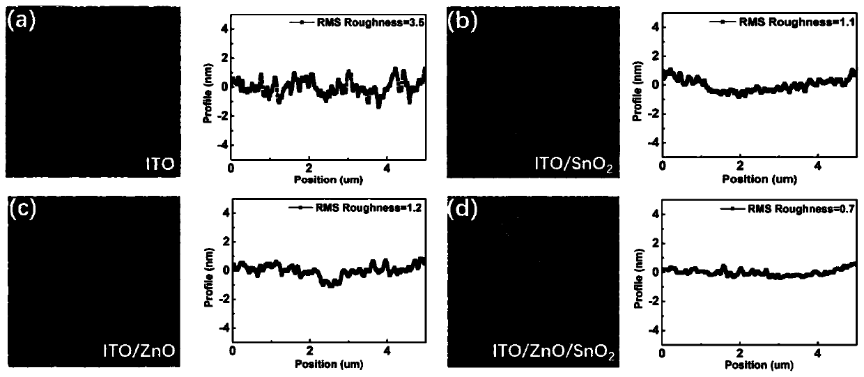
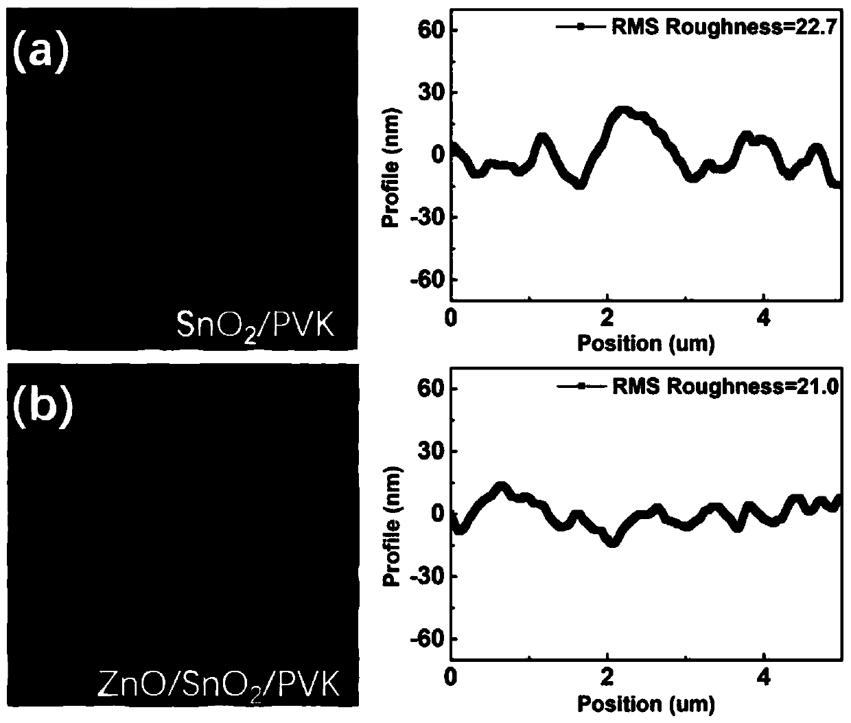
[0061] see image 3 d in and Figure 4 and Figure 5 , with SnO 2 With increasing thickness of the electron transport layer, SnO 2 The surface roughness of the electron transport layer did not change significantly, indicating that the ZnO modification layer and the SnO 2 The electron transport layer cooperates, when SnO 2 After the electron transport layer is spin-coated on the ZnO modified layer, it does not only fill the pits on the surface of the ZnO modified layer, but also acts on the surface of the SnO through the ZnO modified layer. 2 The surface of the electron transport layer is affected, and the effect is in the SnO 2 The case where the thickness of the electron transport layer is increased can also be clearly manifested.

[0062] see Figure 6 , the main diffraction peaks include 14.1°, 19.9°, 24.5°, 28.3° ...


PUM


Abstract

The invention discloses a ZnO modified SnO2-based perovskite solar cell and a preparation method thereof. The solar cell includes a conductive glass layer, a ZnO modification layer, a SnO2 electron transport layer, a perovskite layer, a hole transport layer and a metal electrode layer which are sequentially layered, wherein the ZnO modification layer does not directly modify contact surfaces of the SnO2 electron transport layer and the perovskite layer, but is reversely disposed on a side of the SnO2 electron transport layer away from the perovskite layer, so a surface of the SnO2 electron transport layer close to the perovskite layer is modified, and roughness of the SnO2 electron transport layer is reduced. The solar cell is advantaged in that roughness reduction of the SnO2 electron transport layer further increases the number of crystal grains of the perovskite, competitive growth among the grains reduces roughness of the perovskite layer, moreover, the ZnO modification layer can directly improve interface contact between the SnO2 electron transport layer and the conductive glass layer.

Description

【Technical field】 [0001] The present invention relates to a kind of SnO modified by ZnO 2 A perovskite-based solar cell and a preparation method thereof belong to the field of perovskite. 【Background technique】 [0002] Since 2009, perovskite solar cells (PSCs) have been widely favored by researchers, mainly because perovskite materials have the characteristics of direct band gap, high absorption coefficient, and long carrier transmission distance. At present, the photoelectric conversion efficiency (PCE) of perovskite solar cells has exceeded 23%. Among them, electron transport materials that transport electrons while blocking holes have attracted extensive attention of researchers. The current mainstream electron transport layer includes titanium oxide, tin oxide, zinc oxide, etc. Among them, SnO that can be processed at low temperature 2 Gradually replace TiO which requires high temperature sintering 2 , has become the focus of research by researchers. [0003] Howe...

Claims


Application Information

Patent Timeline
Patent Type & Authority Applications(China)
IPC IPC(8): H01L51/46H01L51/44H01L51/42H01L51/48B82Y30/00B82Y40/00
CPCB82Y30/00B82Y40/00H10K71/00H10K30/35H10K30/80H10K2102/00Y02E10/549
Inventor 诸跃进林鎏金
Owner COLLEGE OF SCI & TECH NINGBO UNIV
Why Eureka
Try Eureka