
Radial fixed-bed dehydration reactor

A radial fixed bed and reactor technology, applied in chemical instruments and methods, hydrocarbon production from oxygen-containing organic compounds, organic chemistry, etc., can solve problems affecting reactor uniformity, blockage of distribution holes, long process, etc., to achieve Effects of avoiding thermal decomposition, reducing olefin polymerization, and improving device yield

Pending Publication Date: 2019-10-25
常州瑞凯化工装备有限公司
View PDF2 Cites 0 Cited by
  • Summary
  • Abstract
  • Description
  • Claims
  • Application Information

AI Technical Summary

Problems solved by technology

[0011] 2. The dehydration of organic alcohols to olefins is a molecular reaction, and the lower reaction pressure is more conducive to the dehydration reaction. Therefore, negative pressure operations are generally used in the process to maximize the conversion rate of organic alcohols, but negative pressure operations are used It also puts forward higher requirements on the resistance drop of the dehydration catalytic bed
[0013] 4. In the co-oxidation propylene oxide plant, due to the long process and many reactions, the organic alcohol raw material before entering the dehydration reactor has many impurities, including oxygen-containing alcohols, aldehydes, esters, phenols, ethers, and non-alcoholic alcohols. Oxygen-containing olefins, alkanes, etc. Many of these impurities are more active than organic alcohol co-products. When the materials are heated and enter the catalyst bed, they will be dehydrated preferentially, and the generated olefins are more likely to polymerize and coke, which will cause radial reactors. The distribution hole of the inlet distribution pipe is partially or even massively blocked, which affects the uniformity of the reactor and generates a large number of by-products

Method used


Image

  • Radial fixed-bed dehydration reactor
  • Radial fixed-bed dehydration reactor
  • Radial fixed-bed dehydration reactor

Examples


Embodiment 1

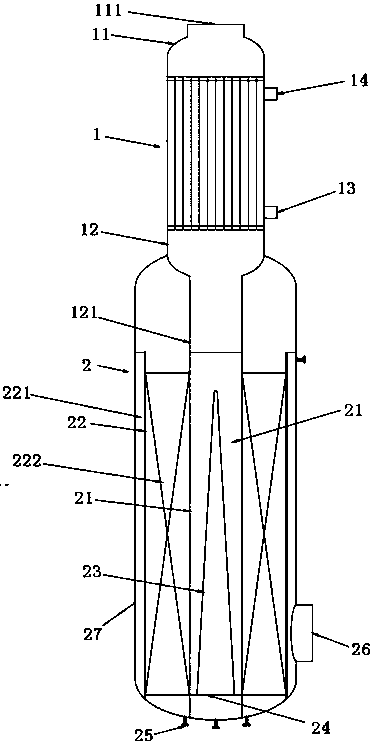
[0040] Embodiment one, such as figure 1 Shown: the present invention relates to a radial fixed-bed dehydration reactor, comprising an inlet heating section 1 and a radial reaction section 2 .

[0041] Such as figure 1 As shown: the air inlet heating section 1 adopts a shell-and-tube heat exchanger, which is provided with an upper head 11 and a lower head 12, the upper head 11 is provided with a tube-side air inlet 111 of the air inlet heating section, and the lower head 12 is provided with a pipe side air outlet 121; the shell side of the intake heating section is provided with a heat medium inlet 13 and a heat medium outlet 14. The pipe-side air outlet 121 of the inlet heating section is connected with the air inlet of the radial reaction section, that is, the air inlet of the central air distribution pipe 21 .

[0042] In the present invention, the inlet heating section 1 and the radial reaction section 2 can be integrated and compactly arranged, and of course they can als...

Embodiment 2

[0047] Embodiment two, such as figure 2 Shown: In this embodiment, on the basis of Embodiment 1, an axial reaction section 3 is added, and the axial reaction section 3 is located between the inlet heating section 1 and the radial reaction section 2; the axial reaction section 3 includes the The head 31, the axial catalytic bed layer 32 and the axial lower head 33, the axial upper head 31 is provided with a feed port correspondingly connected with the lower head tube side gas outlet 121 of the inlet heating section; the axial lower seal The head 33 is provided with a discharge port 331 connected to the air inlet of the central gas distribution pipe 21 , and the shell at the inlet end of the radial reaction section 2 is connected to the axially lower head 33 by welding.

[0048] In this embodiment, the distance between the upper layer of the axial catalytic bed layer and the upper axial head is 2m, and the distance between the lower layer of the axial catalytic bed layer and th...

Embodiment 3

[0054] Embodiment three, such as image 3 Shown: In this embodiment, the reactor described in Example 2 is used to form the first dehydration reactor, and the reactor described in Example 1 is used to form the second dehydration reactor, and the two form a joint production.

[0055] The above-mentioned equipment is applied to the 200,000 tons / year propylene oxide co-production 450,000 tons / year styrene plant, and the oxidation reactor for dehydrating phenylethanol to styrene. The specific dimensions are shown in Table 2.

[0056] Table 2 Main dimensions of the two reactors in Example 3

[0057] project Dimensions, mm Number of units 2 units diameter D 3600 Height (cylinder) H 18050 / 13700 Reaction basket diameter do 3100 Distributor diameter di 1000 Diversion cone and base angle α 86 °

[0058] The flow process of this embodiment is that the phenylethanol raw material enters the vaporizer to be vaporized, and then enters the...


PUM


Abstract

The invention relates to a radial fixed-bed dehydration reactor. The radial fixed-bed dehydration reactor comprises an inlet gas heating-up section and a radial reacting section, wherein the inlet gasheating-up section is provided with an upper closure head and a lower closure head; the radial reacting section comprises a shell body, a central gas distributing pipe and a radial reaction basket with a plurality of vent holes, a plurality of gas distributing holes are formed in the side wall of the central gas distributing pipe, an annular space between the central gas distributing pipe and theshell body is divided into a radial reaction chamber and a gas collection chamber through the radial reaction basket, and a catalyst bed layer is formed in the radial reaction chamber; a central flowdeflection cone is arranged in the central gas distributing pipe, and a tip of the central flow deflection cone corresponds to an inlet of the central gas distributing pipe; and the shell body at aninlet end of the radial reacting section is welded to the lower closure head of the inlet gas heating-up section, and a gas inlet of the radial reacting section is connected with a pipe side gas outlet of the inlet gas heating-up section. The radial fixed-bed dehydration reactor can more efficiently adapt to a dehydration reaction of organic alcohols, and thus, alkene products have higher selectivity.

Description

technical field [0001] The invention belongs to the field of chemical equipment, and in particular relates to a radial fixed-bed reactor, which is especially suitable for co-products in co-oxidation propylene oxide devices: for example, 1-phenylethyl alcohol, dimethyl benzyl alcohol, tert-butanol, etc. dehydration reaction. Background technique [0002] Using organic hydrogen peroxide as an oxygen carrier (such as ethylbenzene hydroperoxide, tert-butyl hydroperoxide, and cumene hydroperoxide) to oxidize propylene to obtain propylene oxide and styrene, that is, the Haakon method is As everyone knows, there are industrialized devices at present. [0003] A typical co-oxidation propylene oxide co-production process includes the following steps: [0004] (a) the organic matter reacts with the oxygen in the oxygen-containing gas to generate organic matter hydrogen peroxide; [0005] (b) organic matter hydrogen peroxide reacts with propylene to generate propylene oxide and orga...

Claims


Application Information

Patent Timeline
IPC IPC(8): B01J8/04C07C1/24C07C15/46C07C15/44C07C11/08
CPCB01J8/04C07C1/24C07C15/46C07C15/44C07C11/08
Inventor 吴非克张文明徐志刚
Owner 常州瑞凯化工装备有限公司
Learn More