Iron-carbon micro-electrolysis filler and preparation method thereof

A technology of iron-carbon micro-electrolysis and iron products, applied in chemical instruments and methods, sterilization/microdynamic water/sewage treatment, water/sewage treatment, etc., can solve the problem of low reflection effect, high maintenance cost and large floor space and other problems, to achieve the effect of good specific surface area, control of production cost, and good porosity

Inactive Publication Date: 2019-12-31
ZHEJIANG UNIV OF TECH
View PDF5 Cites 4 Cited by
  • Summary
  • Abstract
  • Description
  • Claims
  • Application Information

AI Technical Summary

Problems solved by technology

At present, the requirements for micro-electrolysis electrode materials are getting higher and higher in the water treatment process, and the fillers such as iron carbon on the market can no longer meet people's requirements for micro-electrolysis fillers.
The iron carbon made of iron filings and iron shavings is called the first generation of iron carbon, which is prone to problems such as agglomeration of iron filings and clogging of the reaction bed during the water treatment process of this iron carbon.
Iron-carbon fixed bed and fluidized bed are called the second-generation iron-carbon. The iron-carbon water treatment process occupies a large area, high maintenance costs, and iron is easy to corrode and passivate.
The iron-carbon sintered with clay at high temperature is called the third-generation iron-carbon. Although it solves the problems of iron filings agglomeration and passivation, the reflection effect is reduced.

Method used


Image

  • Iron-carbon micro-electrolysis filler and preparation method thereof
  • Iron-carbon micro-electrolysis filler and preparation method thereof
  • Iron-carbon micro-electrolysis filler and preparation method thereof

Examples


Embodiment 1

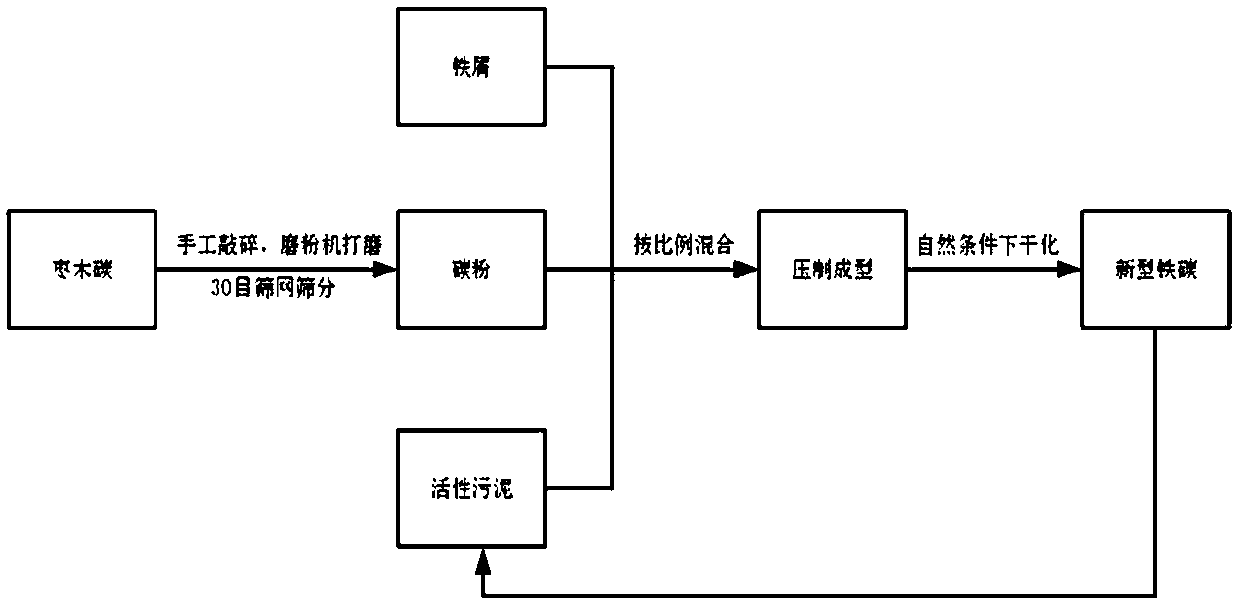
[0039] Iron carbon is made by mixing iron filings (g): carbon powder (g): sludge (ml) = 1:1:0. Without adding activated sludge, it is directly mixed and compacted with carbon powder and iron powder. It can be shaped, and it can be completely dispersed after being gently pinched or put into wastewater.

Embodiment 2

[0041] Iron carbon is made by mixing iron filings (g): carbon powder (g): sludge (ml) = 3:3:6. Soak the prepared iron carbon in the prepared phosphorus-containing wastewater, place it in a shaker, simulate the hydraulic shock in the actual operation, shake continuously for two weeks under the conditions of 90r / min and 20°C, and the filler does not appear slightly broken. Condition.

Embodiment 3

[0043] Iron carbon is made by mixing iron filings (g): carbon powder (g): sludge (ml) = 3:3:9.9. Soak the prepared iron carbon in the prepared phosphorus-containing wastewater, place it in a shaker, simulate the hydraulic shock in the actual operation, shake continuously for two weeks under the conditions of 90r / min and 20°C, and the filler does not break.


PUM

PropertyMeasurementUnit
densityaaaaaaaaaa
densityaaaaaaaaaa
water absorptionaaaaaaaaaa

Abstract

The invention relates to an iron-carbon micro-electrolysis filler; the iron-carbon micro-electrolysis filler takes activated sludge as an adhesive, and is prepared by the following steps: 1) manuallycracking whole section of jujube charcoal into small particles, putting the small particles into a powder mill, grinding into powder, and sieving the powder with a 30-mesh sieve to obtain carbon powder; 2) taking waste iron scraps generated in an iron product machining process as iron powder; 3) taking residual sludge as an adhesive; 4) putting the charcoal powder and the iron powder into a container according to a ratio, and fully and uniformly mixing; 5), adding activated sludge into the mixed charcoal powder and iron powder according to a certain ratio and uniformly stirring; 6), putting the mixed material into a mold, beating for several times, and demolding; and 7), drying after standing in a natural state for 24 h, and thus obtaining the iron-carbon filler. The iron-carbon filler hasthe advantages of simple process, convenient preparation, low cost, energy saving and environmental protection.

Description

technical field [0001] The invention belongs to the technical field of water treatment fillers, and in particular relates to an iron-carbon micro-electrolytic filler and a preparation method thereof. Background technique [0002] Iron-carbon filler, also known as micro-electrolytic filler, iron-carbon micro-electrolytic filler, and internal electrolytic filler, is one of the important conditions for micro-electrolysis technology to treat wastewater. Electrochemical catalytic oxidation of iron-carbon internal electrolytic filler is used to remove phosphorus from wastewater. At present, the requirements for micro-electrolysis electrode materials are getting higher and higher in the process of water treatment, and the fillers such as iron carbon on the market can no longer meet people's requirements for micro-electrolysis fillers. The iron carbon made of iron filings and iron shavings is called the first generation of iron carbon, which is prone to problems such as agglomeratio...

Claims


Application Information

Patent Timeline
Patent Type & Authority Applications(China)
IPC IPC(8): C02F1/461C02F1/467C02F3/32
CPCC02F1/46109C02F1/4672C02F3/32C02F2001/46133
Inventor 李军冯洪波潘增锐谢冬冬韦甦倪永炯
Owner ZHEJIANG UNIV OF TECH
Why Eureka
Try Eureka